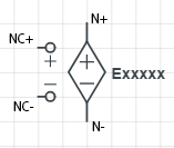
Exxxxx N+ N- NC+ NC- Value
This document gives a brief overview of how dependent sources are accommodated in modified nodal analysis. The description of each type of source is brief, but is followed by an example. Between the description and the example you should be able to figure out how to add dependent sources to your model. You may want to review the MNA algorithm if necessary (especially the role of the various matrices and submatrices), as well as how to use the SCAM program. Note: the example netlists (as well as the MATLAB code) are on GitHub
Voltage controlled voltage sources (VCVS) are defined in a netlist with an element name (that begins with the letter "E"), followed by the two output nodes (N+ and N-), the two controlling nodes (NC+ and NC-) and the gain Value. The output voltage is set to the gain Value multiplied by the difference between the controlling nodes.
\[\left( {{v_{N + }} - {v_{N - }}} \right) = Value \cdot \left( {{v_{NC + }} - {v_{NC - }}} \right)\]
Exxxxx N+ N- NC+ NC- Value
Since the VCVS adds a voltage source to the circuit we also need to add a new unknown, which is the current throught the voltage source (so the B, C, and D submatrices all become larger — review the MNA algorithm if necessary). Recall that currents out of the node are taken to be positive.
The VCVS is demonstrated in the circuit shown
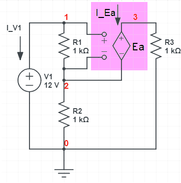
We can analyze with scam and you can see how the VCVS effects the matrices (the netlist is shown near the top of the output).
>> scam

Netlist:
V1 1 0 12
R1 1 2 1000
R2 2 0 1000
R3 3 0 1000
Ea 3 2 1 2 g

The A matrix:
[  1/R1,       -1/R1,    0, 1,  0]
[ -1/R1, 1/R1 + 1/R2,    0, 0, -1]
[     0,           0, 1/R3, 0,  1]
[     1,           0,    0, 0,  0]
[   -Ea,      Ea - 1,    1, 0,  0]

The x matrix:
  v_1
  v_2
  v_3
 I_V1
 I_Ea

The z matrix:
  0
  0
  0
 V1
  0

The matrix equation:
            I_V1 + v_1/R1 - v_2/R1 == 0
 v_2*(1/R1 + 1/R2) - v_1/R1 - I_Ea == 0
                     I_Ea + v_3/R3 == 0
                              v_1 == V1
       v_3 - Ea*v_1 + v_2*(Ea - 1) == 0

The solution:
                                                      v_1 == V1
 v_2 == (R2*V1*(R3 - Ea*R1))/(R1*R2 + R1*R3 + R2*R3 - Ea*R1*R2)
 v_3 == (R3*V1*(R2 + Ea*R1))/(R1*R2 + R1*R3 + R2*R3 - Ea*R1*R2)
     I_V1 == -(V1*(R2 + R3))/(R1*R2 + R1*R3 + R2*R3 - Ea*R1*R2)
  I_Ea == -(V1*(R2 + Ea*R1))/(R1*R2 + R1*R3 + R2*R3 - Ea*R1*R2)
If you look carefully you will see that a variable has been added to the x matrix for the current through the VCVS (labelled "I_Ea") and that the last row of the A matrix defines the relationship between input (controlling) and output voltages for the VCVS, effectively:
\[\left( {v\_3 - v\_2} \right) = Ea \cdot \left( {v\_1 - v\_2} \right)\]Voltage controlled current sources (VCCS) are defined in a netlist with an element name (that begins with the letter "G"), followed by the two output nodes (N+ and N-), the two controlling nodes (NC+ and NC-) and the gain Value. The output current is set to the gain Value multiplied by the difference between the controlling nodes. The circuit equations for nodes N+ and N- (i.e., summing the current at each node to zero) must be changed to account for the new current:
\[\begin{gathered} {\text{node N+ :}}\quad \quad {Value} \cdot \left( {{v_{NC+}} - {v_{NC-}}} \right) + \sum {\left( {{\text{other currents into N+}}} \right) = 0} \hfill \\ {\text{node N- :}}\quad \quad -Value \cdot \left( {{v_{NC+}} - {v_{NC-}}} \right) + \sum {\left( {{\text{other currents into N-}}} \right) = 0} \hfill \\ \end{gathered} \]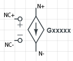
Gxxxxx N+ N- NC+ NC- Value
Recall that currents out of the node are taken to be positive.
The only matrix that changes is the G matrix. If you examine the defining equations above you see that in the row of G associated with "N+" we add "+Value" to the column associated with "NC+" and "-Value" to the node associated with "NC-". In the row of G associated with "N-" we add "-Value" to the column associated with "NC+" and "+Value" to the node associated with "NC-".
The VCCS is demonstrated in the circuit shown
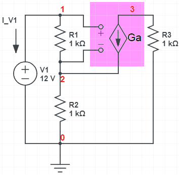
We can analyze with scam and you can see how the VCCS effects the matrices (the netlist is shown near the top of the output).
>> scam

Netlist:
V1 1 0 12
R1 1 2 1000
R2 2 0 1000
R3 3 0 1000
Ga 3 2 1 2 g

The A matrix:
[        1/R1,            -1/R1,    0, 1]
[ - Ga - 1/R1, Ga + 1/R1 + 1/R2,    0, 0]
[          Ga,              -Ga, 1/R3, 0]
[           1,                0,    0, 0]

The x matrix:
  v_1
  v_2
  v_3
 I_V1

The z matrix:
  0
  0
  0
 V1

The matrix equation:
                   I_V1 + v_1/R1 - v_2/R1 == 0
 v_2*(Ga + 1/R1 + 1/R2) - v_1*(Ga + 1/R1) == 0
                 Ga*v_1 - Ga*v_2 + v_3/R3 == 0
                                     v_1 == V1

The solution:
                                       v_1 == V1
 v_2 == (R2*V1*(Ga*R1 + 1))/(R1 + R2 + Ga*R1*R2)
      v_3 == -(Ga*R1*R3*V1)/(R1 + R2 + Ga*R1*R2)
                I_V1 == -V1/(R1 + R2 + Ga*R1*R2)
Since no new voltage sources are added to the circuit, the matrices don't change size, however the G submatrix must be altered to account for the current from the VCCS.
For the current controlled voltage source (CCCS) the controlling quantity is current. You will recall that the only currents that are calculated by the MNA algorithm are currents through voltage sources. Therefore, the controlling current must be the current through one of the voltage sources. It is this voltage source that is used in the netlist as the controlling element — but keep in mind it is the current through voltage source that is important. (Note: if you reqquire a controlling current that is not initailly the current through a voltage source, you need to add a zero voltage source to the circuit (see example) so that current will be calculated.). The CCVS is defined in a netlist with an element name (that begins with the letter "H"), followed by the two output nodes (N+ and N-), the name of the voltage source whose current is the controlling current, and the gain Value. For this element, the output voltage is set to the gain Value multiplied by the controlling current.
\[\left( {v_{N+} - v_{N-}} \right) = Value \cdot I\_Vxxxxx\]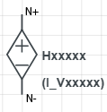
Hxxxxx N+ N- Vxxxxx Value
Since the CCVS adds a voltage source to the circuit we also need to add a new unknown, which is the current throught the voltage source (so the B, C, and D submatrices all become larger — review the MNA algorithm if necessary). Recall that currents out of the node are taken to be positive.
The use of a CCVS is demonstrated in the circuit shown whose netlist is given by:
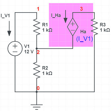
We can analyze with scam and you can see how the CCVS effects the matrices (the netlist is shown near the top of the output).
>> scam


Netlist:
V1 1 0 12
R1 1 2 1000
R2 2 0 1000
R3 3 0 1000
Ha 3 2 V1 r

The A matrix:
[  1/R1,       -1/R1,    0,   1,  0]
[ -1/R1, 1/R1 + 1/R2,    0,   0, -1]
[     0,           0, 1/R3,   0,  1]
[     1,           0,    0,   0,  0]
[     0,          -1,    1, -Ha,  0]

The x matrix:
  v_1
  v_2
  v_3
 I_V1
 I_Ha

The z matrix:
  0
  0
  0
 V1
  0

The matrix equation:
            I_V1 + v_1/R1 - v_2/R1 == 0
 v_2*(1/R1 + 1/R2) - v_1/R1 - I_Ha == 0
                     I_Ha + v_3/R3 == 0
                               v_1 == V1
               v_3 - v_2 - Ha*I_V1 == 0

The solution:
                                                 v_1 == V1
  v_2 == (R2*V1*(Ha + R3))/(R1*R2 + R1*R3 + R2*R3 + Ha*R2)
 v_3 == -(R3*V1*(Ha - R2))/(R1*R2 + R1*R3 + R2*R3 + Ha*R2)
   I_V1 == -(V1*(R2 + R3))/(R1*R2 + R1*R3 + R2*R3 + Ha*R2)
    I_Ha == (V1*(Ha - R2))/(R1*R2 + R1*R3 + R2*R3 + Ha*R2)
As you can see the B, C, and D submatrices have been enlarged to account for the new unknown variable (I_Ha, the current through the CCVS output), and the D matrix has been altered such that the last equation is effectively:
\[\left( {v\_3 - v\_2} \right) = Ha \cdot I\_V1\]as desired.
For the current controlled current source (CCCS) the controlling quantity is current. You will recall that the only currents that are calculated by the MNA algorithm are currents through voltage sources. Therefore, the controlling current must be the current through one of the voltage sources. It is this voltage source that is used in the netlist as the controlling element — but keep in mind it is the current through voltage source that is important. (Note: if you reqquire a controlling current that is not initailly the current through a voltage source, you need to add a zero voltage source to the circuit (see example) so that current will be calculated.). The CCCS is defined in a netlist with an element name (that begins with the letter "F"), followed by the two output nodes (N+ and N-), the name of the voltage source whose current is the controlling current, and the gain Value. For this element, the output current is set to the gain Value multiplied by the controlling current. The circuit equations for nodes N+ and N- (i.e., summing the current at each node to zero) must be changed to account for the new current (in this equation "I_Vxxxxx" is the current through the voltage source "Vxxxxx" (defined elsewhere in the netlist):
\[\begin{gathered} {\text{node N+ :}}\quad \quad Value \cdot I\_Vxxxxx + \sum {\left( {{\text{other currents into N+}}} \right) = 0} \hfill \\ {\text{node N- :}}\quad \quad -Value \cdot I\_Vxxxxx + \sum {\left( {{\text{other currents into N-}}} \right) = 0} \hfill \\ \end{gathered} \]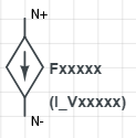
Fxxxxx N+ N- Vxxxxx Value
Recall that currents out of the node are taken to be positive.
Only the B matrix changes. For this element we need to add a current equal to "Value·I_Vxxxxx" to node "N+" and subtract it from node "N-". To do this we find the column of B that correspondes to the voltage source "Vxxxxx". To the row "N+" of this column we add "Value" (so that it multiplies "I_Vxxxxx") which effectively adds "Value·I_Vxxxxx" to that node . Likewise, we subtract "Value" from the row "N-" of this same column of B.
The use of a CCCS is demonstrated in the circuit shown whose netlist is given by (in this case the controlling current is the current through "V1"):
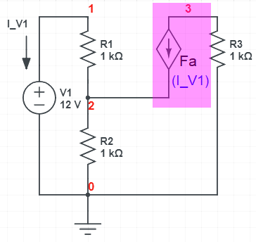
We can analyze with scam and you can see how the CCCS effects the matrices (the netlist is shown near the top of the output).
>> scam

Netlist:
V1 1 0 12
R1 1 2 1000
R2 2 0 1000
R3 3 0 1000
Fa 3 2 V1 f

The A matrix:
[  1/R1,       -1/R1,    0,   1]
[ -1/R1, 1/R1 + 1/R2,    0, -Fa]
[     0,           0, 1/R3,  Fa]
[     1,           0,    0,   0]

The x matrix:
  v_1
  v_2
  v_3
 I_V1

The z matrix:
  0
  0
  0
 V1

The matrix equation:
               I_V1 + v_1/R1 - v_2/R1 == 0
 v_2*(1/R1 + 1/R2) - v_1/R1 - Fa*I_V1 == 0
                     v_3/R3 + Fa*I_V1 == 0
                                 v_1 == V1

The solution:
                                  v_1 == V1
 v_2 == -(R2*V1*(Fa - 1))/(R1 + R2 - Fa*R2)
        v_3 == (Fa*R3*V1)/(R1 + R2 - Fa*R2)
              I_V1 == -V1/(R1 + R2 - Fa*R2)
Note the changes to the B submatrix that accounts for the current added to (or subtracted from) the output nodes.
| Circuit Element | Netlist Description |
VCVS |
Exxxxx N+ N- NC+ NC- Value |
VCCS |
Gxxxxx N+ N- NC+ NC- Value |
CCVS |
Hxxxxx N+ N- Vxxxxx Value |
CCCS |
Fxxxxx N+ N- Vxxxxx Value |