This document describes an algorithmic method for generating MNA (Modified Nodal Analysis) equations for systems with only impedances (resistors) and independent voltage and current sources. It consists of several parts:.
Many of the ideas and notation from this page are from Litovski, though the discussion here is quite simpler because only passive elements (e.g., resistors) independent voltage and current sources are considered.
Recall from the previous document that MNA applied to a circuit results in a matrix equation of the form:
\[{\mathbf{Ax = z}}\]We will take n to be the number of nodes (not including ground) and m to be the number of independent voltage sources.
Review the rules for forming MNA matrices (if needed).
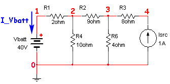
The example given is from Smith, Figure 2.8. First the MNA equations will be derived from the circuit. They will then be derived according to the algorithm in the previous document -- hopefully the results will agree. The nodes and sources have been labeled as required, and the current through the voltage source is defined (as required).

To apply the MNA technique we will need 5 equations (one for each of 4 nodes, and 1 for the independent voltage source). Note that Smith only required 2 equations -- MNA often requires more equations than other techniques, but is amenable to computer solution. By inspection we get:
\[\eqalign{ I\_Vbatt + \frac{{v\_1 - v\_2}}{{R1}} &= 0\quad \quad \;\quad &node\;1 \\ \frac{{v\_2 - v\_1}}{{R1}} + \frac{{v\_2}}{{R4}} + \frac{{v\_3 - v\_2}}{{R2}} &= 0\quad \quad \;\quad &node\;2 \\ \frac{{v\_2 - v\_3}}{{R2}} + \frac{{v\_3}}{{R6}} + \frac{{v\_4 - v\_3}}{{R3}} &= 0\quad \quad \;\quad &node\;3 \\ \frac{{v\_3 - v\_4}}{{R3}} - Isrc &= 0\quad \quad \;\quad &node\;4 \\ v\_1 &= Vbatt\quad \;\,&voltage\;source \\ } \]Using the algorithm, we get:
\[\begin{gathered} {\mathbf{G}} = \left[ {\begin{array}{*{20}{c}} {\frac{1}{{R1}}}&{ - \frac{1}{{R1}}}&0&0 \\ { - \frac{1}{{R1}}}&{\frac{1}{{R1}} + \frac{1}{{R4}} + \frac{1}{{R2}}}&{ - \frac{1}{{R2}}}&0 \\ 0&{ - \frac{1}{{R2}}}&{\frac{1}{{R2}} + \frac{1}{{R6}} + \frac{1}{{R3}}}&{ - \frac{1}{{R3}}} \\ 0&0&{ - \frac{1}{{R3}}}&{\frac{1}{{R3}}} \end{array}} \right],\;{\mathbf{B}} = {{\mathbf{C}}^T} = \left[ {\begin{array}{*{20}{c}} 1 \\ 0 \\ 0 \\ 0 \end{array}} \right],\;{\mathbf{D}} = \left[ 0 \right] \\ {\mathbf{A}} = \left[ {\begin{array}{*{20}{c}} {\frac{1}{{R1}}}&{ - \frac{1}{{R1}}}&0&0&1 \\ { - \frac{1}{{R1}}}&{\frac{1}{{R1}} + \frac{1}{{R4}} + \frac{1}{{R2}}}&{ - \frac{1}{{R2}}}&0&0 \\ 0&{ - \frac{1}{{R2}}}&{\frac{1}{{R2}} + \frac{1}{{R6}} + \frac{1}{{R3}}}&{ - \frac{1}{{R3}}}&0 \\ 0&0&{ - \frac{1}{{R3}}}&{\frac{1}{{R3}}}&0 \\ 1&0&0&0&0 \end{array}} \right] \\ {\mathbf{v}} = \left[ {\begin{array}{*{20}{c}} {v\_1} \\ {v\_2} \\ {v\_3} \\ {v\_4} \end{array}} \right],\;{\mathbf{j}} = \left[ {I\_Vbatt} \right],\quad {\mathbf{x}} = \left[ {\begin{array}{*{20}{c}} {\begin{array}{*{20}{c}} {v\_1} \\ {v\_2} \\ {v\_3} \\ {v\_4} \end{array}} \\ {I\_Vbatt} \end{array}} \right] \\ {\mathbf{i}} = \left[ {\begin{array}{*{20}{c}} 0 \\ 0 \\ 0 \\ {Isrc} \end{array}} \right],\quad {\mathbf{e}} = \left[ {Vbatt} \right],\quad {\mathbf{z}} = \left[ {\begin{array}{*{20}{l}} 0 \\ 0 \\ 0 \\ {Isrc} \\ {Vbatt} \end{array}} \right] \\ \end{gathered} \]Putting these together yields:
\[\begin{gathered} {\mathbf{Ax}} = {\mathbf{z}} \\ or \\ \left[ {\begin{array}{*{20}{c}} {\frac{1}{{R1}}}&{ - \frac{1}{{R1}}}&0&0&1 \\ { - \frac{1}{{R1}}}&{\frac{1}{{R1}} + \frac{1}{{R4}} + \frac{1}{{R2}}}&{ - \frac{1}{{R2}}}&0&0 \\ 0&{ - \frac{1}{{R2}}}&{\frac{1}{{R2}} + \frac{1}{{R6}} + \frac{1}{{R3}}}&{ - \frac{1}{{R3}}}&0 \\ 0&0&{ - \frac{1}{{R3}}}&{\frac{1}{{R3}}}&0 \\ 1&0&0&0&0 \end{array}} \right]\left[ {\begin{array}{*{20}{c}} {\begin{array}{*{20}{c}} {v\_1} \\ {v\_2} \\ {v\_3} \\ {v\_4} \end{array}} \\ {I\_Vbatt} \end{array}} \right] = \left[ {\begin{array}{*{20}{l}} 0 \\ 0 \\ 0 \\ {Isrc} \\ {Vbatt} \end{array}} \right] \\ \end{gathered} \]Careful comparison of this result with the original result verifies that the two solutions are identical.
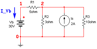
The example given is from Smith, Problem 2.11. First the MNA equations will be derived from the circuit. They will then be derived according to the algorithm in the previous document -- hopefully the results will agree. The nodes and sources have been labeled as required, and the current through the voltage source is defined.

To apply the MNA technique we will need 3 equations (one for each of 2 nodes, and 1 for the independent voltage source). By inspection we get:
\[\eqalign{ I\_Vb + \frac{{v\_1 - v\_2}}{{R1}} &= 0 \quad \quad &node\;1 \\ \frac{{v\_2 - v\_1}}{{R1}} + \frac{{v\_2}}{{R2}} + \frac{{v\_2}}{{R3}} - Is &= 0 \quad \quad &node\;2 \\ v\_1 &= Vb \quad \quad &voltage\;source } \]Using the algorithm, we get:
\[\begin{gathered} {\mathbf{G}} = \left[ {\begin{array}{*{20}{c}} {\frac{1}{{R1}}}&{ - \frac{1}{{R1}}} \\ { - \frac{1}{{R1}}}&{\frac{1}{{R1}} + \frac{1}{{R2}} + \frac{1}{{R3}}} \end{array}} \right],\;{\mathbf{B}} = {{\mathbf{C}}^T} = \left[ {\begin{array}{*{20}{c}} 1 \\ 0 \end{array}} \right],\;{\mathbf{D}} = \left[ 0 \right] \\ {\mathbf{A}} = \left[ {\begin{array}{*{20}{c}} {\frac{1}{{R1}}}&{ - \frac{1}{{R1}}}&1 \\ { - \frac{1}{{R1}}}&{\frac{1}{{R1}} + \frac{1}{{R2}} + \frac{1}{{R3}}}&0 \\ 1&0&0 \end{array}} \right] \\ {\mathbf{v}} = \left[ {\begin{array}{*{20}{c}} {v\_1} \\ {v\_2} \end{array}} \right],\;{\mathbf{j}} = \left[ {I\_Vb} \right],\quad {\mathbf{x}} = \left[ {\begin{array}{*{20}{c}} {\begin{array}{*{20}{c}} {v\_1} \\ {v\_2} \end{array}} \\ {I\_Vb} \end{array}} \right] \\ {\mathbf{i}} = \left[ {\begin{array}{*{20}{c}} 0 \\ {Is} \end{array}} \right],\;{\mathbf{e}} = \left[ {Vb} \right],\quad {\mathbf{z}} = \left[ {\begin{array}{*{20}{c}} {\begin{array}{*{20}{c}} 0 \\ {Is} \end{array}} \\ {Vb} \end{array}} \right] \\ \end{gathered} \]If we apply these results to the MNA equation, we get
\[\begin{gathered} {\mathbf{Ax}} = {\mathbf{z}} \\ or \\ \left[ {\begin{array}{*{20}{c}} {\frac{1}{{R1}}}&{ - \frac{1}{{R1}}}&1 \\ { - \frac{1}{{R1}}}&{\frac{1}{{R1}} + \frac{1}{{R2}} + \frac{1}{{R3}}}&0 \\ 1&0&0 \end{array}} \right]\left[ {\begin{array}{*{20}{c}} {\begin{array}{*{20}{c}} {v\_1} \\ {v\_2} \end{array}} \\ {I\_Vb} \end{array}} \right] = \left[ {\begin{array}{*{20}{c}} {\begin{array}{*{20}{c}} 0 \\ {Is} \end{array}} \\ {Vb} \end{array}} \right] \\ \end{gathered} \]Careful comparison of this result with the original result verifies that the two solutions are identical.
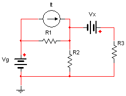
The last example is a bit more involved, it has two voltage sources and one current source. The current source and one of the voltage sources are not grounded.

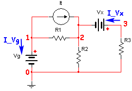
First we must label the nodes and define currents through the voltage sources

To apply the MNA technique we will need 5 equations (one for each of 3 nodes, and 2 for the independent voltage sources). By inspection we get:
\[\eqalign{ I\_Vg + It + \frac{{v\_1 - v\_2}}{{R1}} &= 0\quad \quad \;\quad &node\;1 \\ - It + \frac{{v\_2 - v\_1}}{{R1}} + \frac{{v\_2}}{{R2}} - I\_Vx &= 0\quad \quad \;\quad &node\;2 \\ I\_Vx + \frac{{v\_3}}{{R3}} &= 0\quad \quad \;\quad &node\;2 \\ v\_1 &= Vg\quad \quad \;\,&voltage\;source\;1 \\ v\_3 - v\_2 &= Vx\quad \quad \;\,&voltage\;source\;2 } \]Using the algorithm we get:
\[\begin{gathered} {\mathbf{G}} = \left[ {\begin{array}{*{20}{c}} {\frac{1}{{R1}}}&{ - \frac{1}{{R1}}}&0 \\ { - \frac{1}{{R1}}}&{\frac{1}{{R1}} + \frac{1}{{R2}}}&0 \\ 0&0&{\frac{1}{{R3}}} \end{array}} \right],\;{\mathbf{B}} = {{\mathbf{C}}^T} = \left[ {\begin{array}{*{20}{c}} 1&0 \\ 0&{ - 1} \\ 0&1 \end{array}} \right],\;{\mathbf{D}} = \left[ {\begin{array}{*{20}{c}} 0&0 \\ 0&0 \end{array}} \right] \\ {\mathbf{A}} = \left[ {\begin{array}{*{20}{c}} {\frac{1}{{R1}}}&{ - \frac{1}{{R1}}}&0&1&0 \\ { - \frac{1}{{R1}}}&{\frac{1}{{R1}} + \frac{1}{{R2}}}&0&0&{ - 1} \\ 0&0&{\frac{1}{{R3}}}&0&1 \\ 1&0&0&0&0 \\ 0&{ - 1}&1&0&0 \end{array}} \right] \\ {\mathbf{v}} = \left[ {\begin{array}{*{20}{c}} {v\_1} \\ {v\_2} \\ {v\_3} \end{array}} \right],\;{\mathbf{j}} = \left[ {\begin{array}{*{20}{c}} {I\_Vg} \\ {I\_Vx} \end{array}} \right],\quad {\mathbf{x}} = \left[ {\begin{array}{*{20}{c}} {\begin{array}{*{20}{c}} {v\_1} \\ {v\_2} \\ {v\_3} \end{array}} \\ {\begin{array}{*{20}{c}} {I\_Vg} \\ {I\_Vx} \end{array}} \end{array}} \right] \\ {\mathbf{i}} = \left[ {\begin{array}{*{20}{c}} { - It} \\ {It} \\ 0 \end{array}} \right],\;{\mathbf{e}} = \left[ {\begin{array}{*{20}{c}} {Vg} \\ {Vx} \end{array}} \right],\quad {\mathbf{z}} = \left[ {\begin{array}{*{20}{c}} {\begin{array}{*{20}{c}} { - It} \\ {It} \\ 0 \end{array}} \\ {\begin{array}{*{20}{c}} {Vg} \\ {Vx} \end{array}} \end{array}} \right] \\ \end{gathered} \]If we apply these results to the MNA equation, we get
\[\begin{gathered} {\mathbf{Ax}} = {\mathbf{z}} \\ or \\ \left[ {\begin{array}{*{20}{c}} {\frac{1}{{R1}}}&{ - \frac{1}{{R1}}}&0&1&0 \\ { - \frac{1}{{R1}}}&{\frac{1}{{R1}} + \frac{1}{{R2}}}&0&0&{ - 1} \\ 0&0&{\frac{1}{{R3}}}&0&1 \\ 1&0&0&0&0 \\ 0&{ - 1}&1&0&0 \end{array}} \right]\left[ {\begin{array}{*{20}{c}} {\begin{array}{*{20}{c}} {v\_1} \\ {v\_2} \\ {v\_3} \end{array}} \\ {\begin{array}{*{20}{c}} {I\_Vg} \\ {I\_Vx} \end{array}} \end{array}} \right] = \left[ {\begin{array}{*{20}{c}} {\begin{array}{*{20}{c}} { - It} \\ {It} \\ 0 \end{array}} \\ {\begin{array}{*{20}{c}} {Vg} \\ {Vx} \end{array}} \end{array}} \right] \\ \end{gathered} \]Careful comparison of this result with the original result verifies that the two solutions are identical.