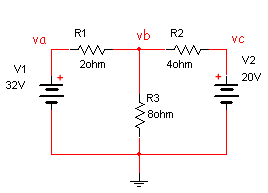
Though the node voltage method and loop current method are the most widely taught, another powerful method is modified nodal analysis (MNA). MNA often results in larger systems of equations than the other methods, but is easier to implement algorithmically on a computer which is a substantial advantage for automated solution. To use modified nodal analysis you write one equation for each node not attached to a voltage source (as in standard nodal analysis), and you augment these equations with an equation for each voltage source. To be more specific, the rules for standard nodal analysis are shown below:
To apply the node voltage method to a circuit with n nodes (with m voltage sources), perform the following steps (after Rizzoni).
The difficulty with this method comes from having to consider the effect of voltage sources. Either a separate equation is written for each source, or the supernode method must be used.
The rules for modified nodal analysis are given by:
To apply the node voltage method to a circuit with n nodes (with m voltage sources), perform the following steps (after DeCarlo/Lin).
Note: I will only discuss independent current and voltage sources. Dependent sources are a simple extension. See Litovski or DeCarlo/Lin for reference.
As an example consider the circuit below (from the previous document)
Consider the circuit shown below (Step 1 has already been applied)

Apply step 2 (currents through the voltage sources with current from positive node to negative node):
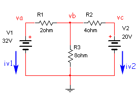
Apply step 3 (with positive currents out of the node):
\[\eqalign{ Node\;a:&\quad {i_{v1}} + \frac{{{v_a} - {v_b}}}{{{R_1}}} = 0 \\ Node\;b:&\quad \frac{{{v_b} - {v_a}}}{{{R_1}}} + \frac{{{v_b}}}{{{R_3}}} + \frac{{{v_b} - {v_c}}}{{{R_2}}} = 0 \\ Node\;c:&\quad {i_{v2}} + \frac{{{v_c} - {v_b}}}{{{R_2}}} = 0 \\ } \]Apply step 4:
\[\eqalign{ v_a = V_1 \\ v_c = V_2 } \]Apply step 5:
\[\eqalign{ i_{v1} + \frac{v_a - v_b}{R_1} &= 0 \\ \frac{v_b - v_a}{R_1} + \frac{v_b}{R_3} + \frac{v_b - v_c}{R_2} &= 0 \\ i_{v2} + \frac{v_c - v_b}{R_2} &= 0 \\ v_a &= V_1 \\ v_c &= V_2 } \]or
\[\left[ {\begin{array}{*{20}{c}} {\frac{1}{{{R_1}}}}&{ - \frac{1}{{{R_1}}}}&0&1&0 \\ { - \frac{1}{{{R_1}}}}&{\frac{1}{{{R_1}}} + \frac{1}{{{R_2}}} + \frac{1}{{{R_3}}}}&{ - \frac{1}{{{R_2}}}}&0&0 \\ 0&{ - \frac{1}{{{R_2}}}}&{\frac{1}{{{R_2}}}}&0&1 \\ 1&0&0&0&0 \\ 0&0&1&0&0 \end{array}} \right]\left[ {\begin{array}{*{20}{c}} {{v_a}} \\ {{v_b}} \\ {{v_c}} \\ {{i_{v1}}} \\ {{i_{v2}}} \end{array}} \right] = \left[ {\begin{array}{*{20}{c}} 0 \\ 0 \\ 0 \\ {V1} \\ {V2} \end{array}} \right]\]Now all that is left is to solve the 5x5 set of equations (recall that the nodal analysis method resulted in just 1 equation, though in that case we did some substitutions along the way). Solving the 5x5 equation is difficult by hand, but not so with a computer.
If you'll recall, the nodal analysis method became a bit more difficult when one or more of the voltage sources was not connect to ground. Let's repeat Example 2 of the previous page with MNA. Here the circuit is repeated with steps 1 and 2 completed:
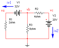
Steps 3 and 4
\[\eqalign{ \frac{v_a}{R_1} - i_{v1} &= 0 \\ i_{v1} + \frac{v_b}{R_3} + \frac{v_b - v_c}{R_2} &= 0 \\ i_{v2} + \frac{v_c - v_b}{R_2} &= 0 \\ v_b - v_a &= V_1 \\ v_c &= V_2 } \]Step 5
\[\left[ {\begin{array}{*{20}{c}} {\frac{1}{{{R_1}}}}&0&0&{ - 1}&0 \\ 0&{\frac{1}{{{R_2}}} + \frac{1}{{{R_3}}}}&{ - \frac{1}{{{R_2}}}}&1&0 \\ 0&{ - \frac{1}{{{R_2}}}}&{\frac{1}{{{R_2}}}}&0&1 \\ { - 1}&1&0&0&0 \\ 0&0&1&0&0 \end{array}} \right]\left[ {\begin{array}{*{20}{c}} {{v_a}} \\ {{v_b}} \\ {{v_c}} \\ {{i_{v1}}} \\ {{i_{v2}}} \end{array}} \right] = \left[ {\begin{array}{*{20}{c}} 0 \\ 0 \\ 0 \\ {V1} \\ {V2} \end{array}} \right]\]The fact that V1 is not grounded presented no difficulty at all.
Let's consider one more example, this time with a current source (this example is from Litovski). Steps 1 and 2 have been completed.
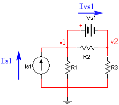
Now complete steps 3 and 4:
\[\eqalign{ -I_{s1} + \frac{v_1}{R_1} + I_{Vs1} + \frac{v_1 - v_2}{R_2} &= 0\quad \quad &(node\;1) \\ -I_{Vs1} + \frac{v_2 - v_1}{R_2} + \frac{v_2}{R_3} &= 0\quad \quad &(node\;2) \\ v_1 - v_2 &= V_{s1}\quad \quad &(V_{s1}) \\ } \]And finally bring all the know variables to the right hand side and complete step 5:
\[\left[ {\begin{array}{*{20}{c}} {\frac{1}{{{R_1}}} + \frac{1}{{{R_2}}}}&{ - \frac{1}{{{R_2}}}}&1 \\ { - \frac{1}{{{R_2}}}}&{\frac{1}{{{R_2}}} + \frac{1}{{{R_3}}}}&{ - 1} \\ 1&{ - 1}&0 \end{array}} \right]\left[ {\begin{array}{*{20}{c}} {{v_1}} \\ {{v_2}} \\ {{I_{Vs1}}} \end{array}} \right] = \left[ {\begin{array}{*{20}{c}} {{I_{s1}}} \\ 0 \\ {{V_{s1}}} \end{array}} \right]\]If you examine the matrix equations that resulted from the application of the MNA method, several patterns become apparent that we can use to develop an algorithm. All of the circuits resulted in an equation of the form.
\[{\mathbf{Ax = z}}\]Let us examine Example 2. This circuit had 3 nodes and 2 voltage sources (n=3, m=2). The resulting matrix is shown below.
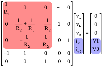
Note that the pink highlighted portion of the A matrix is 3×3 (in general n×n), and includes only known quantities, specifically the values of the passive elements (the resistors). In addition the highlighted portion of the A matrix is symmetric with positive values along the main diagonal, and only negative (or zero) values for the off-diagonal terms. If an element is connected to ground, it only appears along the diagonal; a non-grounded (e.g. R2) appears both on and off the diagonal). The rest of the terms in the A matrix (the non-highlighted portion) contains only ones, negative ones and zeros. Note also that the matrix size is 5x5 (in general (m+n)×(m+n)). For all of the circuits we will analyze (i.e., only passive elements and independent sources), these general observations about the A matrix will always hold.
Now consider the x matrix, the matrix of unknown quantities. It is a 5×1 matrix (in general (n+m)×1). The topmost 3 (in general n) elements are simply the node voltages. The bottom 2 (in general m) elements are the currents associated with the voltage sources.
This brings us to the z matrix that contains only known quantities. It is also a 5×1 matrix (in general (n+m)×1). The topmost 3 (in general n) elements are either zero, or the sum of independent current sources (see example 3 for an case in point). The bottom 2 (in general m) elements are the independent voltage sources.
MNA applied to a circuit with only passive elements (resistors) and independent current and voltage sources results in a matrix equation of the form:
\[{\mathbf{Ax = z}}\]For a circuit with n nodes and m independent voltage sources:
The circuit is solved by a simple matrix manipulation:
\[{\mathbf{x = }}{{\mathbf{A}}^{ - 1}}{\mathbf{z}}\]Though this may be difficult by hand, it is straightforward and so is easily done by computer.
In the next page we will use these observations to describe an algorithm for generating the matrices automatically.