

Contents
One of the most common test inputs used is the unit step function,


The response of a system (with all initial conditions equal to zero at t=0-, i.e., a zero state response) to the unit step input is called the unit step response. If the problem you are trying to solve also has initial conditions you need to include a zero input response in order to obtain the complete response.
If you don't know about Laplace Transforms, there are time domain methods to calculate the step response.
We can easily find the step input of a system from its transfer function. Given a system with input x(t), output y(t) and transfer function H(s)
\[H(s) = \frac{Y(s)}{X(s)}\]the output with zero initial conditions (i.e., the zero state output) is simply given by
\[Y(s) = X(s) \cdot H(s)\]so the unit step response, Yγ(s), is given by
\[Y_\gamma(s)=\frac{1}{s} \cdot H(s)\]Immediately we can determine two characteristics of the unit step response, the initial and final values, of the step response by invoking the initial and final value theorems.
Initial Value Theorem: $\mathop {\lim }\limits_{t \to {0^ + }} f(t) = \mathop {\lim }\limits_{s \to \infty } s \cdot F(s)$
Final Value Theorem: $\mathop {\lim }\limits_{t \to \infty } f(t) = \mathop {\lim }\limits_{s \to 0} s \cdot F(s)$
So,
\[\begin{gathered} \mathop {\lim }\limits_{t \to {0^ + }} {y_\gamma }(t) = \mathop {\lim }\limits_{s \to \infty } s \cdot {Y_\gamma }(s) = \mathop {\lim }\limits_{s \to \infty } s \cdot \frac{1}{s}H(s) = \mathop {\lim }\limits_{s \to \infty } H(s) \\ \mathop {\lim }\limits_{t \to \infty } {y_\gamma }(t) = \mathop {\lim }\limits_{s \to 0} s \cdot {Y_\gamma }(s) = \mathop {\lim }\limits_{s \to 0} s \cdot \frac{1}{s}H(s) = \mathop {\lim }\limits_{s \to 0} H(s) \\ \end{gathered} \]Often we simplify this and write,
\[\begin{gathered} {y_\gamma }({0^ + }) = H(\infty ) \\ {y_\gamma }(\infty ) = H(0) \\ \end{gathered} \]
First we will consider a generic first order system, then we will proceed with several examples. Consider a generic first order transfer function given by

where a, b and c are arbitrary real numbers and either b or c (but not both) may be zero. To find the unit step response, we multiply H(s) by 1/s

and take the inverse Laplace transform using Partial Fraction Expansion.
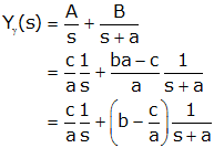
so

We now note several features about this equation, namely

Thus we can write the general form of the unit step response as:
\[\begin{align}This last equation is important. It states that if we can determine the initial value of a first order system (at t=0+), the final value and the time constant, that we don't need to actually solve any equations (we can simply write the result). Likewise if we experimentally determine the initial value, final value and time constant, then we know the transfer function.
The unit step response of a first order system is:
\[\begin{align}This is depicted on the graph below. Note that the input starts at yγ(0+) and asymptotically approaches yγ(∞);
The time constant of first order systems is often easy to find. The time constants of some typical first order systems are given in the table below:
| Type of System | Time Constant | |
| translating friction-mass |
m/b | |
| translating friction-spring |
b/k | |
| rotating friction-flywheel |
J/Br | |
| rotating friction-spring |
Br/Kr | |
| resistor-capacitor | R·C | |
| resistor-inductor | L/R | |
| thermal | R·C |
If the input force of the following system is a unit step, find v(t). Also shown is a free body diagram.
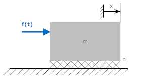

Solution:
The differential equation describing the system is

so the transfer function is determined by taking the Laplace transform (with zero initial conditions) and solving for V(s)/F(s)

To find the unit step response, multiply the transfer function by the unit step (1/s) and solve by looking up the inverse transform in the Laplace Transform table (Asymptotic exponential)

Note: Remember that v(t) is implicitly zero for t<0 (i.e., it is multiplied by a unit step function).
For m=b=1, we get:

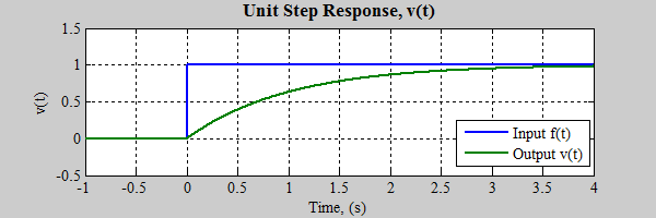
Alternate Solution (without inverse Laplace Transform)
From the transfer function we infer that:

Using the general form of the step response of a first order system we get

Alternate Solution (without Laplace Transform)
The system starts at rest and the velocity of a mass can't change instantaneously (with a finite input) so v(0+)=0. The final velocity is independent of the mass (because there is no inertial force at constant velocity, so f(∞)=bv(∞), or v(∞)=f(∞)/b=1/b. The time constant of a friction-mass system is m/b. So

If the input force of the following system is a step of amplitude X0 meters, find y(t). Also shown is a free body diagram. Note the input is not a unit step, but has a magnitude of X0. Therefore all system outputs must also be scaled by X0.

Solution:
The differential equation describing the system is

so the transfer function is determined by taking the Laplace transform (with zero initial conditions) and solving for Y(s)/X(s)

To find the unit step response, multiply the transfer function by the step of amplitude X0 (X0/s) and solve by looking up the inverse transform in the Laplace Transform table (Exponential)
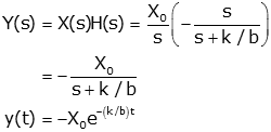
Note: Remember that v(t) is implicitly zero for t<0 (i.e., it is multiplied by a unit step function).
For k=b=1, X0=2 we get:

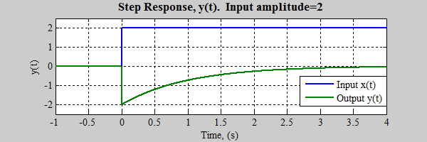
(Note: input and output are in different directions because they were defined that way in system drawing)
Alternate Solution (without inverse Laplace Transform)
From the transfer function we infer that:

Note: we have to multiply y(0+) and y(∞) by X 0 because the input is unit step multiplied by X0.
Using the general form of the step response of a first order system we get
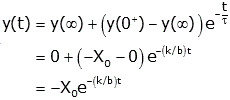
Alternate Solution (without Laplace Transform)
The length of the daspot can't change instantaneously (with a finite force) so x(0+)=-X0. The final position is independent of the dashpot (because there is no friction force at zero velocity, so x(∞)=0. The time constant of a friction-spring system is b/k. So

If the input voltage, ein(t), of the following system is a unit step, find eout(t).
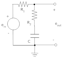
Solution:
First we find the transfer function. We note that the circuit is a voltage divider with two impedances
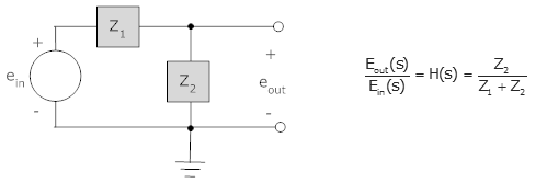
where Z1 is R1 and Z2 is R 2 in series with C.
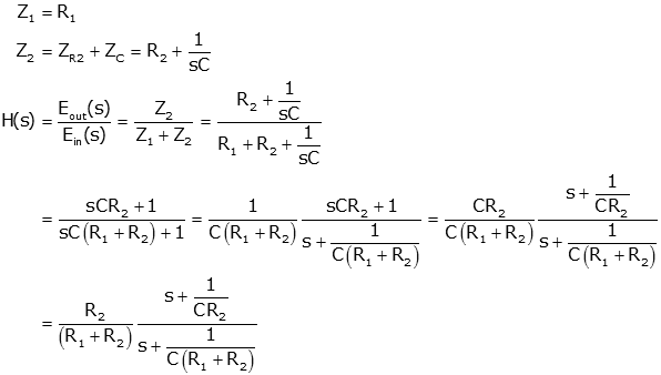
To find the unit step response, multiply the transfer function by the unit step (1/s) and the inverse Laplace transform using Partial Fraction Expansion..
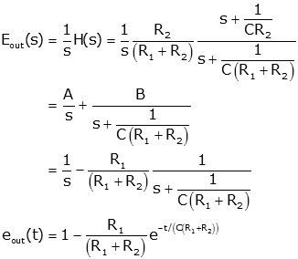
With R1=R2=1kOhm and C=1μF, we get

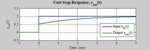
Alternate Solution (without inverse Laplace Transform)
From the transfer function we infer that:
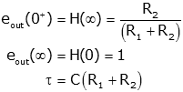
Using the general form of the step response of a first order system we get
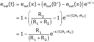
Clearly that was much simpler than the previous solution (using partial fraction expansion)
Alternate Solution (without Laplace Transform)
At t=0+ the capacitor has no voltage across it so we have a simple voltage divider and eout(0+)=R2/(R1+R2). As t→∞ no current flows because of the capacitor so eout(∞)=ein(∞)=1. From the perspective of the capacitor, the resistors are in series, so the time constant is C·Req=C(R1+R2). Therefore, as before,
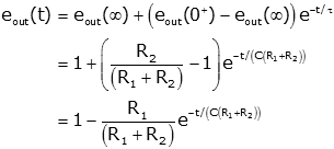
Note that all of the examples above follow the generic form of the response of a first order system to a sudden (i.e., step) change:
\[\begin{align}As you would expect, the response of a second order system is more complicated than that of a first order system. Whereas the step response of a first order system could be fully defined by a time constant (determined by pole of transfer function) and initial and final values, the step response of a second order system is, in general, much more complex. As a start, the generic form of a second order transfer function is given by:
\[\frac{{Y(s)}}{{X(s)}} = H(s) = \frac{{a{s^2} + bs + c}}{{{s^2} + ds + e}}\]where a, b, c, d and e are arbitrary real numbers and at least one of the numerator terms is non-zero.
It is impossible to totally separate the effects of each of the five numbers in the generic transfer function, so let's start with a somewhat simpler case where a=b=0. Then we can rewrite the transfer function as
\[H(s) = \frac{c}{{{s^2} + ds + e}} = K\frac{{\omega _0^2}}{{{s^2} + 2\zeta {\omega _0}s + \omega _0^2}}\]where we have introduced three constants
\[\eqalign{Note: the term ζ is read as "zeta." Also note that ω0 is always a positive number.
The choice of these constants may seem arbitrary, but we will soon show that the choice simplifies the mathematics, and that all three constants have a physical interpretation that helps give insights into a system. We call this the prototype second order lowpass system (because the frequency response of this system is "lowpass," don't worry if you don't know what that means yet).
To find the unit step response of the system we first multiply by 1/s (the Laplace transform of a unit step input)
\[{Y_\gamma }(s) = \frac{1}{s}H(s) = \frac{1}{s}K\frac{{\omega _0^2}}{{{s^2} + 2\zeta {\omega _0}s + \omega _0^2}}\]Before we can solve for yγ(t) let us first try to factor the denominator into first order terms. The roots of the denominator of the transfer function, s2+2ζω0s+ω02, are determined from the quadratic equation
\[s = \frac{{ - 2\zeta {\omega _0} \pm \sqrt {{{\left( {2\zeta {\omega _0}} \right)}^2} - 4\omega _0^2} }}{2} = - \zeta {\omega _0} \pm {\omega _0}\sqrt {{\zeta ^2} - 1} \]The value of ζ determines five cases of interest that are given special names (whose origin will soon be apparent):
| Name | Value of ζ | Roots of s | Characteristics of "s" |
| Overdamped | ζ>1 | $s = - \zeta {\omega _0} \pm {\omega _0}\sqrt {{\zeta ^2} - 1} $ | Two real and negative roots |
| Critically Damped |
ζ=1 | s = $- {\omega _0}$ | A single (repeated) negative root |
| Underdamped | 0<ζ<1 | $s = - \zeta {\omega _0} \pm j{\omega _0}\sqrt {1 - {\zeta ^2}}$ |
Complex conjugate (j = √-1); |
| Undamped | ζ=0 | $s = \pm j{\omega _0}$ | Pure imaginary (no real part) |
| Exponential Growth |
ζ<0 | $s = - \zeta {\omega _0} \pm {\omega _0}\sqrt {{\zeta ^2} - 1}$ |
Roots may be complex or real, but the real part of s is always positive |
The first three cases are most important, and the last two will be discussed only briefly in what follows.
In the overdamped case we have two real poles of the transfer function (or zeros of the characteristic equation) at
\[s = - \zeta {\omega _0} \pm {\omega _0}\sqrt {{\zeta ^2} - 1} \]For convenience, we will refer to these as α1 and α2 (these are shown in a pole-zero diagram at the right)
\[\begin{gathered}and note that
\[{\alpha _1} \cdot {\alpha _2} = {\omega _0}\left( { \zeta + \sqrt {{\zeta ^2} - 1} } \right) \cdot {\omega _0}\left( { \zeta - \sqrt {{\zeta ^2} - 1} } \right) = \omega _0^2\left( {{\zeta ^2} + - \left( {{\zeta ^2} - 1} \right) + \zeta \sqrt {{\zeta ^2} - 1} - \zeta \sqrt {{\zeta ^2} - 1} } \right) = \omega _0^2\]
The transfer function may now be written as
\[H(s) = K\frac{{\omega _0^2}}{{{s^2} + 2\zeta {\omega _0}s + \omega _0^2}} = K\frac{{{\alpha _1} \cdot {\alpha _2}}}{{\left( {s + {\alpha _1}} \right)\left( {s + {\alpha _2}} \right)}}\]
and the unit step response as
\[{Y_\gamma }(s) = \frac{1}{s}H(s) = \frac{1}{s}K\frac{{{\alpha _1} \cdot {\alpha _2}}}{{\left( {s + {\alpha _1}} \right)\left( {s + {\alpha _2}} \right)}}\]We can look this form up as the "asymptotic double exponential" in the Laplace transform table (or do an inverse Laplace transform using partial fraction expansion) to get:
\[{y_\gamma }(t) = K\left( {1 - \frac{{{\alpha _2}{e^{ - \alpha_1 t}} - {\alpha _1}{e^{ - \alpha_2 t}}}}{{{\alpha _2} - {\alpha _1}}}} \right)\]In terms of damping coefficient and natural frequency, this becomes
\[\begin{gathered} {y_\gamma }(t) = K\left( {1 - \frac{{{\omega _0}\left( {\zeta - \sqrt {{\zeta ^2} - 1} } \right){e^{ - {\omega _0}\left( {\zeta + \sqrt {{\zeta ^2} - 1} } \right)t}} - {\omega _0}\left( {\zeta + \sqrt {{\zeta ^2} - 1} } \right){e^{ - {\omega _0}\left( {\zeta - \sqrt {{\zeta ^2} - 1} } \right)t}}}}{{{\omega _0}\left( {\zeta - \sqrt {{\zeta ^2} - 1} } \right) - {\omega _0}\left( {\zeta + \sqrt {{\zeta ^2} - 1} } \right)}}} \right) \\ = K\left( {1 + \frac{{\left( {\zeta - \sqrt {{\zeta ^2} - 1} } \right){e^{ - {\omega _0}\left( {\zeta + \sqrt {{\zeta ^2} - 1} } \right)t}} - \left( {\zeta + \sqrt {{\zeta ^2} - 1} } \right){e^{ - {\omega _0}\left( {\zeta - \sqrt {{\zeta ^2} - 1} } \right)t}}}}{{2\sqrt {{\zeta ^2} - 1} }}} \right) \\ \end{gathered} \]This is quite a complicated expression, but note several things
The effects of ζ and ω0 on the shape of the response are discussed later. You can experiment with how the pole locations affect the step resonse with an interactive demo.
To find the response of the critically damped case we proceed as with the overdamped case. For ζ=1 the roots of the denominator of the transfer function are both at s=-ω0 (an alternative notations has poles at s=-α) so the transfer function can be written as
\[H(s) = K\frac{{\omega _0^2}}{{{s^2} + 2{\omega _0}s + \omega _0^2}} = K\frac{{\omega _0^2}}{{{{\left( {s + {\omega _0}} \right)}^2}}} = K\frac{{{\alpha ^2}}}{{{{\left( {s + \alpha } \right)}^2}}}\]
This has a repeated pole at s=-ω0 (or equivalently, s=-α as shown on the pole-zero diagram.
\[{Y_\gamma }(s) = \frac{1}{s}H(s) = \frac{1}{s}K\frac{{\omega _0^2}}{{{{\left( {s + {\omega _0}} \right)}^2}}} = \frac{1}{s}K\frac{{{\alpha ^2}}}{{{{\left( {s + \alpha } \right)}^2}}}\]
This is the "asymptotic critically damped" form in the Laplace transform table, so
\[\eqalign{We can note several characteristics of this response:
You can experiment with how the pole location affects the step resonse with an interactive demo.
For the underdamped case we use the transfer function to find the step response in the Laplace domain. The pole locations can either be written in terms of ζ and ω0, or in terms of their real and imaginary parts (α and ωd),
\[H(s) = K\frac{{\omega _0^2}}{{{s^2} + 2{\omega _0}s + \omega _0^2}} = K\frac{{{\alpha ^2} + \omega _d^{^2}}}{{{{\left( {s + \alpha } \right)}^2} + \omega _d^{^2}}}\]These pole locations are shown on the diagram at right. Note that -α is the real part of the pole location, and ±jωd is the imaginary part. Or we can say that ω0 is the distance from the origin, and the angle the pole makes with the horizontal axis is determined by ζ (θ=acos(ζ)); We can relate these two representations by:
\[\eqalign{ {\omega _d} &= {\omega _0}\sqrt {1 - {\zeta ^2}} \\ \alpha &= \zeta \omega _0} \]The step response is
\[{Y_\gamma }(s) = \frac{1}{s}H(s) = \frac{1}{s}K\frac{{\omega _0^2}}{{{s^2} + 2{\omega _0}s + \omega _0^2}} = \frac{1}{s}K\frac{{{\alpha ^2} + \omega _d^{^2}}}{{{{\left( {s + \alpha } \right)}^2} + \omega _d^{^2}}}\]We find this form in the Laplace transform table ("Prototype 2nd order lopass step response"), so
\[\eqalign{ {y_\gamma }(t) &= K\left( {1 - \frac{1}{{\sqrt {1 - {\zeta ^2}} }}{e^{ - \zeta {\omega _0}t}}\sin \left( {{\omega _0} {\sqrt {1 - {\zeta ^2}} } t + \theta} \right)} \right) \\ &= K\left( {1 - \frac{\sqrt{{{\alpha ^2} + \omega _d^2}}}{{{\omega _d}}}{e^{ - \alpha t}}\sin \left( {{\omega _d}t + \theta} \right)} \right) \\ \theta &= \operatorname{acos} \left( \zeta \right) = \operatorname{atan} \left( {\frac{{{\omega _d}}}{\alpha }} \right)} \]There is a lot of information in this expression. Several important characteristics of the equation include:
The topic of the effects of ζ and ω0 on the shape of the response is an important one but is discussed later.
You can experiment with how the pole location affects the step resonse with an interactive demo.
When the damping coefficient is zero the system is said to be undamped. The roots of the denominator of the transfer function are at s=±jω0 so the transfer function is
\[H(s) = K\frac{{\omega _0^2}}{{{s^2} + \omega _0^2}} = K\frac{{\omega _0^2}}{{\left( {s + j{\omega _0}} \right)\left( {s - j{\omega _0}} \right)}}\]which give a step response
\[{Y_\gamma }(s) = \frac{1}{s}H(s) = \frac{1}{s}K\frac{{\omega _0^2}}{{{{\left( {s + {\omega _0}} \right)}^2}}}\]This is a special case of the "Prototype 2nd order lopass step response" form in the Laplace transform table with ζ=0. So we get:
\[{y_\gamma }(t) = K\left( {1 - \sin \left( {{\omega _0}t + \pi } \right)} \right) = K\left( {1 - \cos \left( {{\omega _0}t} \right)} \right)\]As expected from the name, the undamped system (ζ=0) has no damping and oscillates forever as the graph below shows.
If we consider the case where ζ is negative, we can write the transfer function in terms of the two roots of the denominator of the transfer function
\[\eqalign{ H(s) &= K\frac{{\omega _0^2}}{{{s^2} + 2\zeta {\omega _0}s + \omega _0^2}} = K\frac{{{\alpha _1} \cdot {\alpha _2}}}{{\left( {s + {\alpha _1}} \right)\left( {s + {\alpha _2}} \right)}} \\ {\alpha _1} &= - \zeta {\omega _0} + {\omega _0}\sqrt {{\zeta ^2} - 1} = {\omega _0}\left( { - \zeta + \sqrt {{\zeta ^2} - 1} } \right) \\ {\alpha _2} &= - \zeta {\omega _0} - {\omega _0}\sqrt {{\zeta ^2} - 1} = {\omega _0}\left( { - \zeta - \sqrt {{\zeta ^2} - 1} } \right) } \]
We determine the unit step response by multiplying H(s) by 1/s (a unit step input), and performing a partial fraction expansion (assuming, for now, that α 1 and α2 are not equal):
\[\eqalign{ {Y_\gamma }(s) &= \frac{1}{s}H(s) = \frac{1}{s}K\frac{{{\alpha _1} \cdot {\alpha _2}}}{{\left( {s + {\alpha _1}} \right)\left( {s + {\alpha _2}} \right)}} \\ &= \frac{{{A_1}}}{s} + \frac{{{A_2}}}{{s + {\alpha _1}}} + \frac{{{A_3}}}{{s + {\alpha _2}}} \\ {y_\gamma }(t) &= {A_1} + {A_2}{e^{ - {\alpha _1}t}} + {A_3}{e^{ - {\alpha _2}t}}} \]
Note we have not calculated the values of A1, A2, and A3, but their precise values are unimportant to the argument being made; i.e., that the solution grows exponentially.
Since the real parts of α1 and α2 are negative, this solution grows exponentially as t increases. If α 1 and α2 are complex (as shown in the pole-zero diagram), the solution oscillates as it grows. For the types of systems we will discuss, this behavior is rare. However, they are important in the topic of "Control Theory.".
The second order lowpass transfer function is given by
\[{H_{LP}}\left( s \right) = {H_{0,LP}}\frac{{\omega _0^2}}{{{s^2} + 2\zeta {\omega _0}s + \omega _0^2}}\]
The graph below shows the effect of ζ on the unit step response of a second order system, for positive values of ζ, with H0,LP=1. For ζ>1 the system is overdamped, and does not oscillate (it also does not oscillate for ζ=1). But for ζ<1 the system is underdamped and oscillate more and more as ζ→0.
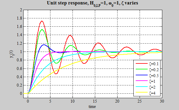
Some notes about this image (that are true as long as ζ>0):
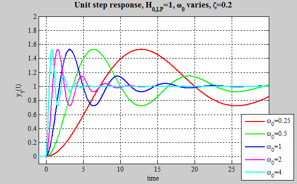
The graph below shows the effect of ω0 on the step response of a second order system. As you can see the shape of the system is unchanged as ω0 varies, but the speed changes (note that the amplitude of first, second, third... peaks are equal, independent of ω0, only their timing changes). As ω0 increases, the speed of the system increases. If ω0 doubles, the speed of the system doubles. But ω0 does not change the shape of the response (this is because ω0 and t always occur as a pair, ω0·t, son increasing ω0 simply increases the product ω0·t at each value of t).
The graph below shows the effect of ζ on the step response of a second order system, for positive and negative values of ζ. For positive values of ζ the response decays with time. For ζ=0, there is no damping (the system is said to be undamped). For negative values of ζ the response actually grows with time. We won't run into many situations like this, but they can occur in certain situations in systems that have energy being added. Notice that the final value isn't defined when ζ≤0.
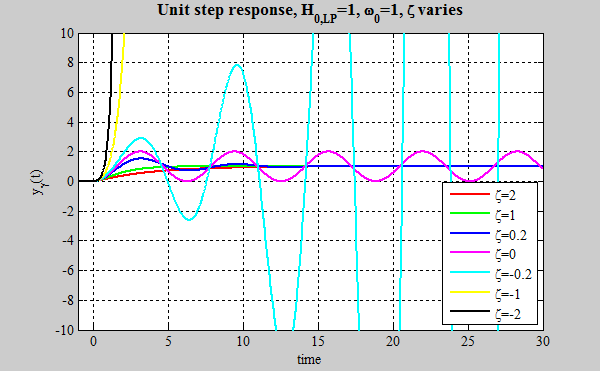
Go to http://lpsa.swarthmore.edu/SecondOrder/SOI.html for an interactive demo
The second order highpass system
\[{H_{HP}}\left( s \right) = {H_{0,HP}}\frac{{{s^2}}}{{{s^2} + 2\zeta {\omega _0}s + \omega _0^2}}\]has many of the same characteristics as the second order lowpass, with some differences as well.

Similarities (marked with "✓") and differences (marked with "✗") to the lowpass response include:
The second order bandpass system
has many of the same characteristics as the second order lowpass and highpass, with some differences as well.
\[{H_{BP}}\left( s \right) = {H_{0,BP}}\frac{{2\zeta {\omega _0}s}}{{{s^2} + 2\zeta {\omega _0}s + \omega _0^2}}\]Similarities (marked with "✓") and differences (marked with "✗") to other second order responses include:
Other proper second order systems will have somewhat different step responses, but some similarities (marked with "✓") and differences (marked with "✗") include:
In a proper system the order of the numerator is less than or equal to that of the denominator. The numerator of a proper second order system will be two or less.
The step responses of higher order systems are harder to generalize about. For example, a third order system can have:
It becomes even more complicated for fourth order systems (which can have repeated complex conjugate roots...). However, even with higher order systems it is still often possible to make useful approximations to first or second order system. The most common way to do that is to use the dominant pole approximation, discussed below.
A more detailed description is at http://lpsa.swarthmore.edu/PZXferStepBode/DomPole.html, including an interactive demo .
Consider an overdamped second order system (and its step response).

If the magnitude of β is very large compared to α (typically if β/α>5) we will write write approximations for the transfer function and step response. The approximation of the transfer function is perhaps not obvious at this point (If you understand Bode plots, make plots of the exact and approximate functions - they are close to equal while the transfer function is large. If you don't know Bode plots, don't worry - it's not important here), but the approximation of yγ(t) is straightforward.

The graph below (left) shows the exact step response (red) and the dominant pole approximation (green) for α=1 and β=5. Though not a perfect match, the exact and approximate responses are pretty close. The pole-zero plot shows that the pole that we kept for our approximation, i.e., the dominant pole, is the one that is closer to the origin. (Note: one of the poles of the exact (red) system is hidden beneath that of the approximate (green) system.)

If we increase β to 10, the approximation is even better, the dominant pole is close (relatively) to the origin than in the previous case.

The dominant pole approximation can also be applied to higher order systems. Here we consider a third order system with one real root, and a pair of complex conjugate roots.

In this case the test for the dominant pole compare "α" against "ζω0". This is because ζω0 is the real part of the complex conjugate root (we only compare the real parts of the roots when determining dominance because it is the real part that determines how fast the response decreases). Note that the DC gain of the exact system and the two approximate systems are equal.
In the examples below, the second order pole has ζ=0.4 and ω0=1 (which yields roots with a real part of -0.4 and an imaginary part of +/-0.92j). There are three sets of graphs. In all three graphs the exact response is in red, the approximate response in which the first order pole is assumed to dominate is in green, and the approximate response in which the second order poles are assumed to dominate is in blue.
In the first set of graphs α=0.1 and the real pole dominates (the response is very similar to a first order response). The blue graph (in which the second order poles are assumed to dominate) is obviously a bad approximation. Looking at the Bode plot, it is clear that the exact and first order response are similar while the gain is substantial and only vary when the system is highly attenuating (at high frequencies). The pole-zero map shows that the real part of the first order response is much closer to zero than the real part of the complex conjugate poles.

In the second set of graphs α=4 and the complex conjugate poles (whose real part is much closer to the origin than that of the complex poles; see pole-zero plot) dominate. The system response looks very much like the second order approximation (and not much like the first order approximation). Note that the scale of these graphs is different than that of the previous set.

In the third set of graphs α=0.4 and none of the poles are dominant and the resulting response is obviously more complicated than a simple first or second order response.

This section is not yet finished