 (translating system equivalent:
 )
)Contents
The discussions on this page follow closely, and draw on, the techniques used to model translating mechanical systems. It is assumed that you are familiar with those techniques. We can also combine translating and rotating systems as discussed here.
For rotating mechanical systems
 (translating system equivalent:
 )
)
If we consider the J·α term to be a torque, we are left with D'Alembert's law
 (translating system equivalent)

We will call the J·α term D'Alembert's torque, or inertial torque. The inertial torque is always in a direction opposite to the defined positive direction.
Equations of motion for translating mechanical system depend on the application of D'Alembert's law. Using this principle we say that the sum of all torques on an object is equal to zero,

but we must also take the inertial torque (J·α) as one of these torques. This inertial torque is in the opposite direction from the defined positive direction.
We can apply D'Alembert's law to develop equations of motion for rotating mechanical systems through the use of free body diagrams. To do this we draw a free body diagram for each unknown position in a system. This is very similar to the way this was done for translating mechanical systems.
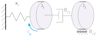
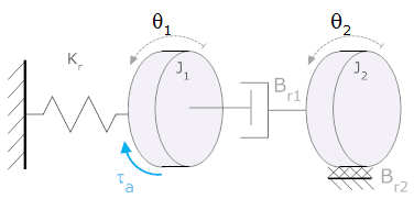
In the system shown one flywheel (J1) is attached by a flexible shaft (Kr) to ground (the unmoving wall) and has an applied torque, τa. A second flywheel (J2) is driven by friction between the two flywheels (Br1). The second flywheel also has friction to the ground (Br2). Derive equations of motion for the system shown.

Solution: First we must define our variables of motion. In this case there are two - the angles of the flywheel. It is generally a good idea to define the variables in the same direction, so we arbitrarily define them as positive in the counterclockwise direction.

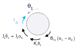
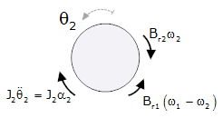
We now create our free body diagrams
| Free body diagram at θ1 | Free body diagram at θ2 |
|
There are 4 torques acting:
|
There are 3 torques acting:
|
 |
 |
 |
 |
It is possible to go directly from the system diagram to a state space model. Details are here system diagram to a state space model.
Thus far we have only developed the differential equations that represent a system. To solve the system, the model must be put into a more useful mathematical representation such as transfer function or state space. Details about developing the mathematical representation are here.
© Copyright 2005 to 2019 Erik Cheever This page may be freely used for educational purposes.
Erik Cheever Department of Engineering Swarthmore College