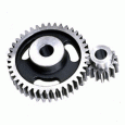
photograph from: http://www.geardesign.co.uk/spur-gears.htm
Contents
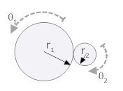
Gears perform many functions, in this section we look at gears that increase or reduce angular velocity (while simultaneously decreasing or increasing torque, such that energy is conserved). In many ways gears act in rotating systems as do levers in translating systems. A picture of gears is shown below, along with a schematic representation.


photograph from: http://www.geardesign.co.uk/spur-gears.htm
We will specify gears by their radii. When you buy gears you normally specify the number of teeth and the number of teeth per inch (or centimeter). These two measures are equivalent: the number of teeth and teeth per inch give the circumference, which in turn determines the radius. If the number of teeth are doubled, the radius is doubled.
If we consider two gears in equilibrium and in contact with each other, we can two very useful relationships.
First we note the geometric relationship that results from the path that the arc lengths along their circumference must be equal as the gears turn.
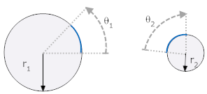
Since the arc lengths (shown with a heavy blue line) must be equal
r1θ1 = r2θ2 = arc length
If we had defined θ2 in the opposite direction, this expression would have a negative sign (r1θ1 = -r2θ2).
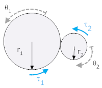
We derive a second relationship from a torque balance. Before we can do so we must define a force between the gears termed a "contact force." This force must be equal and opposite across the interface between the two gears, but its direction is arbitrary. We start by drawing free body diagrams with a contact force where the gears meet.
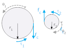
The contact force is tangent to both gears and so produces a torque that is equal to the radius times the force.
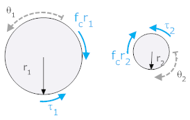
We can do a torque balance on each of the two gears
| Gear 1 | Gear 2 | |
 |
 |
We are not usually interested in fc, so we remove from the equations and we get

It is easy to show that the same relationship exists even if the contact forces are defined in the opposite direction (up on gear 1, down on gear 2).
In the system below, a torque, τa, is applied to gear 1 (with moment of inertia J1). It, in turn, is connected to gear 2 (with moment of inertia J2) and a rotational friction Br. The angle θ1 is defined positive clockwise, θ2 is defined positive clockwise. The torque acts in the direction of θ1.
Derive a differential equation for the system below in terms of θ1 (i.e., θ2 and fc should not be in the final result).
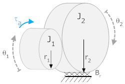
We start by drawing free body diagrams, including a contact force that we will arbitrarily choose to be down on J1 and up on J2. The directions of the reaction forces due to inertia and friction are chosen, as always, opposite to the defined positive direction.

We convert the force to a torque (note: we could have skipped the previous step and done this directly)

This yields the two equations of motion

We can easily solve for fc and eliminate it from the equations, but we also need to eliminate θ2. To do this we use the relationship between θ1 and θ2 (from equal arc lengths).
r1θ1 = -r2θ2
Note that we have a negative sign here because of the way θ1 and θ2 were defined (if θ1 moves in the positive direction, then θ2 is negative). When you use the arc length expression you must be careful of signs.

We can put this into the equation for J1 and solve (in standard form with the output (θ1) on the left, and the input (τa) on the right.

Note: the same result is obtained independent of the chosen direction for θ2 and fc.
The final result from the example is important deserves some notice. The multiplication of J2 and Br by the square of the ratio of the radii is a well known, and general phenomenon. If a load is attached to a system through gears, the perceived effect is multiplied by the square of the ratio of the radii. We can use this to our advantage to make a load appear smaller (if we have a weak driving torque - for example, a small motor). The reason bicycles have gears is so that the load perceived by the bicycle rider can be kept relatively constant even as s/he goes up or down hills.
Note that if we combine the geometric relationship

with the torque relationship,

the product of torque and velocity becomes:

You will see on the next web page that the product of angular velocity and torque is power. So the last equation simply states that power is preserved across a set of gears. The gears allow one to trade torque for angular velocity (i.e., if the gears are of unequal size, the larger gear will experience higher torque but lower angular velocity than the smaller gear).
While this document doesn't discuss pulleys directly, the concepts are closely related (i.e., you must perform a torque balance around the pivot). Pulleys are discussed here.
Systems that have parts that rotate and translate are handled in much the same way as with gears:
Cannon, Dynamics of Physical Systems, 1967, McGraw-Hill, Section 5.3, page 152
The process will be illustrated with an example.
Derive equations of motion for the system shown along with an expression relating horizontal position to angle of rotation. There is a force, fa, applied to a mass m. A uniform cylinder sits on top of the mass and is free to roll and translate, but it rolls without slipping.
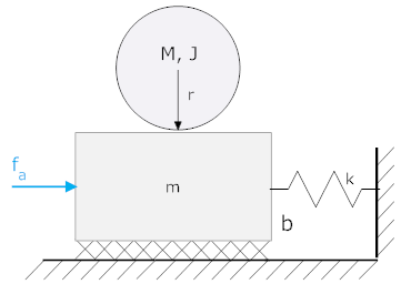
First we need to define positions, in this case three of them. We need to define one for the position of the mass, m, and one for the angle through which the cylinder has turned about its center. We also need to define one for the lateral position of the cylinder.
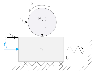
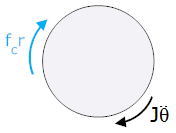
Now we can draw free body diagrams (again, we need three), and write the equations of motion. Here we have taken fc to be to the right on m, and to the left on the cylinder. Torques are taken about the center of mass.
| Freebody diagram at x1 |
 |
 |
| Freebody around θ |
 |
 |
| Freebody diagram at x2 |
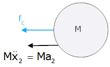 |
 (note: this uses mass of cylinder) |
The last thing we need is a relationship between position and arc length for the cylinder. In this case it is not so obvious, but is easily found with a little thought.
Therefore, by superposition
r·θ=x1-x2
When solving problems with gears, you always need to include two facts:
If you are not using both of these relationships, you probably won't be able to solve the problem.
The motion of an body can be separated into two independent component, translation and rotation. If an element both rotates and translates a separate freebody diagram is needed for each component.