


Contents
As with translating mechanical systems, there are three fundamental physical elements that comprise rotating mechanical system: inertia elements, springs and friction elements.
The quantities used in rotating systems are very similar to those in translating
systems. The table below lists the analogous quantities for rotating and translating
systems. The constitutive equations for inertial elements, springs and friction
elements follow.
| Rotating Systems | Translating Systems | |||
| Quantity | Unit | Quantity | Unit | |
| Moment of Inertia - J | kg-m² | Mass - m | kg | |
| Torque - τ | N-m | Force - f | N | |
| Angle - θ | rad | Length - l | m | |
Angular velocity -
 |
rad/sec | Velocity -
 |
m/s | |
Angular acceleration -
 |
rad/sec² | Acceleration -
 |
m/s² | |
| Spring Constant - Kr | N-m/rad | Spring Constant - k | N/m | |
| Friction Coefficient - Br | N-m-s/rad | Friction Coefficient - g | N-s/m | |
Note that the spring and friction elements for the rotating systems will use capital letters with a subscript r (Kr, Br), while the translating systems will use a lowercase letter.
One of the difficulties in working with rotating systems (as opposed to those that translate) is that there are often multiple ways to make diagrams of the systems. In examples below, a few alternatives are given; you should try to become comfortable with the multiple representations.
In rotating mechanical systems, the inertia elements are masses that rotate and are characterized by moment of inertia. The moment of inertia for some common shapes are given below.
| Shape | Image | Moment of Inertia, J |
| Cylinder, radius=r, mass=m Rotating about center axis |
 |
 |
| Solid Sphere,
radius=r, mass=m Rotating about center |
 |
 |
| Uniform Rod, length=ℓ, mass=m Rotating about end |
 |
 |
| Uniform Rod, length=ℓ, mass=m Rotating about center |
 |
 |
| Mass at end of
massless rod, length=ℓ, mass=m Rotating about end |
 |
 |
The relationship between torque, moment of inertia and angular acceleration is given by:
 (Translating system equivalent:
 )
)
A rotational spring is an element that is deformed (wound or unwound) in direct proportion to the amount of torque applied. Ideal springs have no inertia. The relationship between torque, spring constant and angle is given by:
 (Translating system equivalent:
 )
)
A photo of typical rotational springs is shown. You should be able to visualize how an applied torque to wind (or unwind) the spring would be opposed.
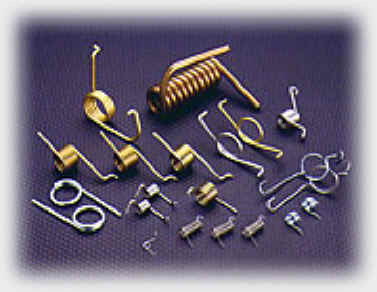
from: http://dudekbock.com/springs.html
A shaft connected between two elements can also act as a rotational spring. Click the start button to see an animation of a flexible shaft (i.e., rotational spring) that is fixed on the left but free to rotate on the right. Note how the shaft twists as the flywheel (with moment of inertia, J), turns (however the rotation doesn't slow because there is no friction).
In practice a rotational spring is drawn as a shaft (with an associated spring constant) or with the same symbol as a translating spring, but with the spring constant as a capital letter with a subscript. Both images below represent the system from the animation, with theta defined positive in the counterclockwise direction.
| Flexible Shaft | 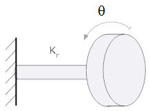 |
| Spring | 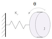 |
As with the translating systems, friction is the most difficult of the three elements to model accurately and we will generally only consider viscous friction. The constitutive equation relating angular velocity, torque and friction coefficient is
 (Translating system equivalent:
 )
)
A rotation friction element often consists of an object moving in a fluid, very similar to the translating dashpot, but with a rotary motion. An example of such a device is used in some exercise equipment. The photo below shows an exercise trainer with a paddlewheel in liquid (the blue circular object). As you exercise, the vanes of the paddlewheel move against the fluid, creating a torque in resistance to your motion.
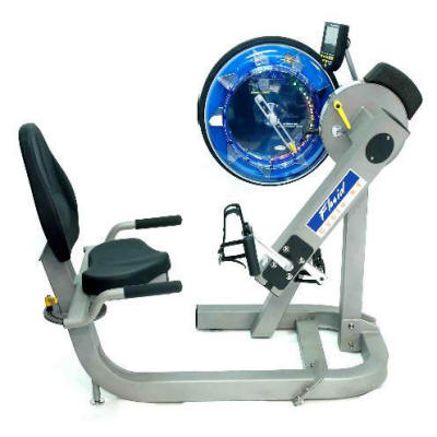
from:
http://www.firstdegreerowers.com/E-720-Cycle-Crosstrainer.asp
There are several ways of drawing these friction elements. Consider the animation shown below with one flywheel (J1) attached by a flexible shaft (Kr) to a wall (as before), but now there is a second flywheel (J2) that is driven by friction between the two flywheels (Br1), and friction to the stationary ground (Br2). J1 starts with an initial value, so it starts oscillating back and forth as the simulation begins. This drives J2, through Br1, but the energy in the system decays over time because energy is lost to the friction.
This system can be shown schematically in a few ways. In the first diagram below, the shaft is shown schematically as a spring, the friction Br1 is drawn as a dashpot, while the friction Br2 is shown as hash marks against ground. In the second diagram the shaft is not drawn as a spring but is shown to be a spring with the label Kr; both friction elements are shown as dashpots. It is important to be comfortable with both drawings (and others that could be drawn).
| Kr=Spring Br1=dashpot Br2=hashmarks |
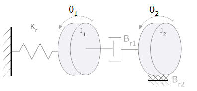 |
| Kr=Flexible Shaft Br1=dashpot Br2=dashpot |
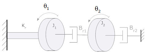 |
Three elements were introduced, springs, friction elements and inertial elements (masses). An ideal linear spring has no mass and a linear relationship between force and elongation. For viscous friction there is a linear relationship between force and velocity. Friction may either be between two surfaces (depicted as hash marks) or between two objects (depicted as a dashpot). An ideal dashpot is also massless. Masses have a linear relationship between force and acceleration.
| Spring: |  |
| Friction: |  |
| Inertia: |  |
© Copyright 2005 to 2019 Erik Cheever This page may be freely used for educational purposes.
Erik Cheever Department of Engineering Swarthmore College