

L is the ratio of lever arms.
There are two commonly used elements, levers and pulleys, that are used to amplify forces or displacements. There is a direct proportionate tradeoff between increase in force and decrease in displacement (or vice-versa), but power is preserved (i.e., the power on the input side of one of these devices is equal to the power out). The behavior and modeling of these elements is the focus of this section.
Contents
Consider a massless lever as shown below.
| Lever | Geometric Relationships |
 |
 L is the ratio of lever arms. |
This states that the ratio of the displacement of x1 relative to x2 is simply the ratio, L, of the two lever arms ℓ1 and ℓ2.
We can find a relationship between forces and displacements by summing the torques around the fulcrum. We also make the small angle approximation so we can assume the force is perpendicular to the lever, and that the motion at the ends of the lever is purely translational in the "x" direction. (Without this approximation we must multiply the magnitude of the force by cos(θ) to get the force perpendicular to the lever.) To do this we add counterclockwise (ccw) torques and subtract clockwise (cw) torques and sum to zero.

This states that the ratio of the force f1 relative to f2 is simply the inverse of the ratio of the two lever arms ℓ1 and ℓ2.
Note that if we combine the force relationship with the velocity relationship, we get:

You will see on the next web page that the product of velocity and force is power. So the last equation simply states that power is preserved; it is the same on both sides of the lever. The lever allows one to trade force for velocity (i.e., if the lever arms are unequal, one side of the lever will experience higher force but lower velocity than the other side).
Develop a mathematical model for the system shown in terms of fa and x1.

We can draw a free-body diagram with horizontal forces and sum the torques (note: we don't care about the force from the fulcrum since its moment arm is zero because we are summing about the fulcrum):
 |
 |
We can rewrite the relationship from the previous example in terms of the position at ℓ1 (associated with displacement x1) at which the force acts. This requires some simple manipulations of the equation of motion from the example.

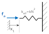
This means that we can create an equivalent system by moving the spring from the location at ℓ2 (associated with displacement x2) to the location at ℓ1 (associated with displacement x1) by multiplying the spring constant by N2 where N=ℓ2/ℓ1, (i.e, N is the ratio of the original moment arm to the moment arm at the new position) In other words, the two systems below are equivalent.
| Original System | Equivalent system |
 |
 |
Likewise, we could write the equations in terms of x2, and develop another equivalent system.
| Rewrite Equations in terms of x2 |
Original System | Equivalent System |
 |
 |
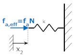 |
To generalize: a spring, mass or friction element can be translated along a lever from a position with a distance from the fulcrum of ℓ1 to a distance of ℓ2 by multiplying by N2, where N=ℓ1/ℓ2,. A force can be moved from a distance of ℓ1 to ℓ2 by multiplying by N. An example will clarify.
Develop an equivalent mechanical model at the position x2.
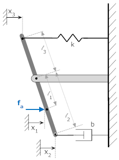
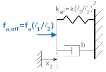
We can effectively move the spring from x3 to x2 by multiplying by (ℓ3/ℓ2)2. We can effectively move the force from x1 to x2 by multiplying by (ℓ1/ℓ2). This yields the equivalent system below (along with free body diagram and mathematical model).
| Equivalent System | Equations of Motion |
 |
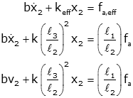 |
Check: As a quick check, let's make free body diagram of original system, sum torques, and simplify. The results must be the same as those above if this technique is correct.
| Free Body Diagram | Equations of Motion |
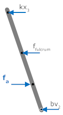 |
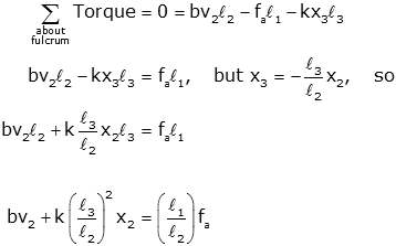 (note negative sign in relationship between x2 and x3) |
A spring, mass or friction element can be translated along a lever from a position with a distance from the fulcrum of ℓ1 to a distance of ℓ2 by multiplying by N2, where N=ℓ1/ℓ2,. A force can be moved from a distance of ℓ1 to ℓ2 by multiplying by N.
Massless pulleys act in very much the same way as the massless lever discussed previously. Consider the system shown below. The pulley has two radii, r1 and r2.
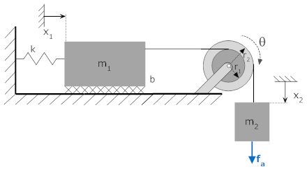
If the pulley moves through an angle θ the distance x1 is given by r1·θ, and the distance x2 is given by r2·θ. Note: The relationship(s) between position and angles are always necessary to solve these systems; if it looks like you don't have enough equations for a solution, make sure you are using those relationships.
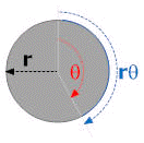 Recall
that the arc length along the circumference of a circle is equal to r·θ where
r is the radius of the circle and theta is the angle around the circle.
If a rope is wrapped around the circle and the circle rotates through an angle
θ, the end of the rope will move by an amount r·θ. It is important to
be careful about the sign of the relationship.
If the rope comes off the top, and the distance is defined as positive to the left, then x1=r·θ. If rope comes off the top and the distance is defined as positive to the right, then x2=r·θ. See below.
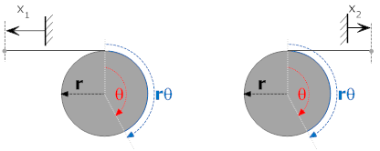
It now becomes apparent that a pulley behaves in the same manner as a lever because the relative displacements are determined by the ratio of the radii (for the lever it was the ratio of the lever arms). However, in this case there is no need to invoke the small angle argument since all motion is purely translational.
A spring, mass or friction element connected to a pulley through a radius r1 can be translated to the another pulley with radius r2 by multiplying by N2, where N=r1/r2. A force can be moved from r1 to r2 by multiplying by N.
Let's demonstrate these ideas with an example to be solved twice. The first solution will sum torques on the pulley, the second time will use effective elements.
Develop a mathematical model in terms of the position x2. Take the equilibrium position of x1 and x2 to be 0 when fa=0.

Since the equilibrium position is defined to be zero we need not consider gravity in our model (reference). Let's draw free body diagrams (one for x1, x2 and θ)
| x1 | θ | x2 | |
| Free Body Diagram |
 T1 is the tension in the upper rope. |
 |
 T2 is the tension in the lower rope. |
| Equations of Motion |
 |
 |
 |
To solve the equations, we also need to use the relationships between x1, x2 and θ.

To solve we will use the torque relationship to solve for T1 in terms of T2, and use the geometric relationship to solve for x1 in terms of x2.

Now we can substitute these into the free body equation at x1, and solve for T2 in terms of x2

Substitute this in the free body equation at x2, and we are done

Repeat the previous example using effective elements.

We can translate the mass m1, friction b, and spring k from x1 to x2 by multiplying by N2, where N=r1/r2.
| x2 | |
| Free Body Diagram |
 |
| Equations of Motion |
 |
The two methods yield equivalent results.
Obviously the second method is computationally simpler; but conceptually more difficult. You should check your results by summing torques until you feel comfortable applying the concept of "effective" elements (either with either levers or pulleys).
© Copyright 2005 to 2019 Erik Cheever This page may be freely used for educational purposes.
Erik Cheever Department of Engineering Swarthmore College