There are three fundamental physical elements that make up translating mechanical system: inertia elements, springs and friction elements. The relationships between force and position (or its derivatives) for these elements are described below.
Contents
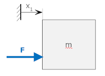
In translating mechanical systems, the inertia elements are masses. A mass will be drawn with a coordinate system as in the drawing below.

In this drawing the coordinate along which the mass translates is x1, and x1 is defined relative to a fixed reference (the vertical line with hash marks to the left). This drawing also shows a force, F, acting on the mass towards the right. Since the force tends to move the mass in the direction of x1, we can write the well known relationship:

where a1 is the second derivative of position with respect to time. The SI units for a mass are kilograms (kg).
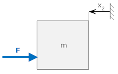
It is important to realize that the defined direction is arbitrary, we could just as easily define the direction in the opposite way. In this case we must change the sign in our equation. The behavior of the system is unchanged regardless of the defined positive direction.

Energy may be stored in a mass as its velocity changes. This energy may be released at a later date.
A linear translating spring is an element that is deformed (shortened or lengthened) in direct proportion to the amount of force applied. Ideal springs have no mass. A photo of a typical spring is shown below along with a schematic representation.
In this diagram the end of spring k1 is determined by the position specified by x1. Unless otherwise specified, the position of x1 is zero when the spring is relaxes (i.e., no force is applied to it).
If we apply a force to the spring to the right, the spring elongates by an amount Δx such that:

Since the displacement, x1, is defined to be zero when the spring is relaxed, we can write:

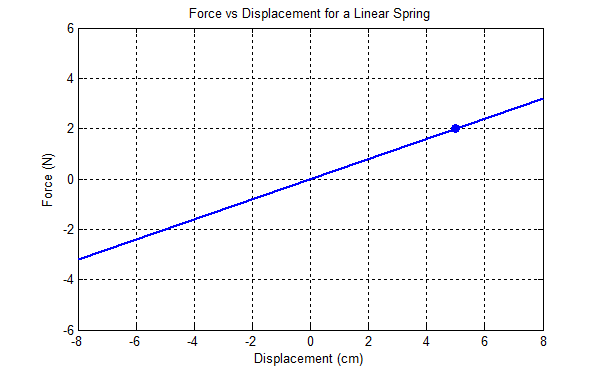
The elongation is proportional to the force. This is the defining relationship for a linear spring. The SI units for the spring consant, k1, are Newtons/meter (N/m). A stiffer spring has a larger spring constant; it takes more force (Newtons) to obtain a given compression. A graph of force vs. displacement for a linear spring is a straight line with a slope equal to the spring constant. In the graph below, it takes 2 N to stretch the spring 5 cm (as shown by the circle on the graph, so the spring constant is
k = 2 N/0.05 m = 40 N/m.
If neither side of the spring is attached to a fixed reference, the situation is slightly more complex. The forces on both ends of the spring must be equal in magnitude and opposite in direction. This way there is no net force on the spring - if there was a net force there would be infinite acceleartion, because the mass of our ideal spring is zero.

Since the elongation of the spring is now x1-x2, we write

In this case the force, F, increases as x1 increases (because an increase in x1 causes elongation of the spring), but decreases as x2 increases (because increasing x2 shortens the spring). This is an example of superposition; because the system is linear the inputs (x1 and x2) can be considered independently.
As with the mass (above) the defined directions are arbitrary. We could have chosen directions as shown below,

which results in an equation where x1 and x2 are added (now an increase in either increases the elongation and, therefore, the force).

Energy may be stored in a spring as its dimension changes. This energy may be released at a later date.
In the real world, springs are not completely linear. For example the spring shown at the top of this section might have a force-displacement curve that looks more like the one below.

This graph has two distinct non-linearities. There is a slight curvature to the graph that indicates that it is increasingly difficult to stretch (or compress) the spring as you move away from the relaxed (no applied force) state of the spring. There is also a hard non-linearity as the spring is compressed enough that the coils actually touch and prevent further compression.
Even though the spring is non-linear, a linear analysis can still be useful. Note that over a small interval (say around 4 cm of displacement) that the curve can be approximated by a straight line (i.e., a linear approximation).
Friction is the most difficult of the three elements to model accurately. However, unless explicitly stated, in the context of linear systems friction is assumed to be viscous friction. This means that the (i.e., the force of the friction is assumed to be proportional to velocity). There are two distinct ways that friction will be shown, as a series of x's between two object, or as a dashpot.
| Sliding Viscous Friction | Dashpot | ||
 |
Symbol |
Picture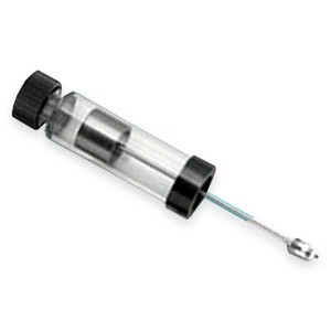 |
|
The friction in the leftmost diagram is indicated by x-shaped hash marks. This indicates friction between two elements that are sliding past each other (perhaps on a film of oil or some other viscous liquid). The rightmost diagram represents a dashpot. In a dashpot a plunger moves in a cylinder filled with a gas or liquid. However the seal on the cylinder is leaky so the fluid can leak. The force required to make the fluid leak is proportional to the velocity of the plunger. (In the dashpot in the photograph, fluid leaks out of the cap on the left as the plunger moves - if the cap is tightened the seal is tighter and the force required to move the plunger increases.) An ideal dashpot has no mass.
For these friction elements, the force is proportional to velocity so that:

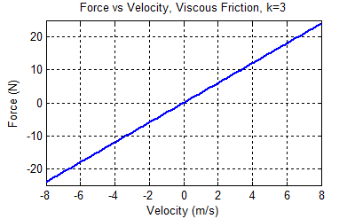
a graph of force vs. velocity for an ideal viscous friction element yields a straight line with a slope of b (N-s/m).

This graph shows a friction coefficient (and slope) of 3 N-s/m. At 2 m/s (the blue dot), the force is 6 N.
In the real world, friction is even harder to model accurately than a spring. For example, it is common in introductory physics classes to introduce friction of two types, static friction and kinetic (or dry, or Coulomb) friction. Also important are viscous friction (described above) and drag. Each is discussed briefly below:
| Description | Graphical Representation |
|
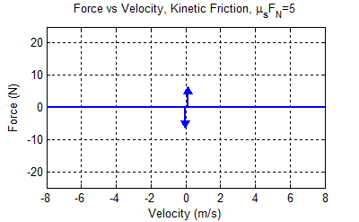
Static Friction:
friction between two objects with no relative
motion between them. The amount of force required to move one
object relative to the other is given by Note: Though the friction only exists for velocity=0 the two arrows are shown slightly offset from the origin to indicate that they are active when the force is in the direction of the offset. In this graph a static friction force of of up to 5 N exists when the force is such that it will cause the mass to move in the positive direction. |
 |
|
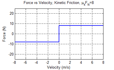
Kinetic friction:
friction between two objects moving relative to
each other. The force due to kinetic friction opposes the
velocity, but its magnitude is constant and independent of the velocity. |
 |
|
Viscous friction:
friction between two objects moving relative to
each other (this is the friction discussed above). The force due to kinetic friction opposes and is
proportional to the velocity. |
 |
|
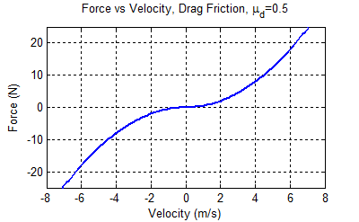
Drag:
friction experienced by an object moving through a fluid
(often air or water). This force is proportional to the square of
the velocity, and opposed to the direction of the velocity. |
 |
In a practical situation, the actual friction will be some combination of the friction types mentioned above (and probably some even more complicated relationships). For the purposes of this document, all friction will be assumed to be viscous unless stated otherwise.
Energy is not stored in friction elements. Instead heat is generated and released to the environment.
Three elements were introduced, springs, friction elements and inertial elements (masses). An ideal linear spring has no mass and a linear relationship between force and elongation. For viscous friction there is a linear relationship between force and velocity. Friction may either be between two surfaces (depicted as hash marks) or between two objects (depicted as a dashpot). An ideal dashpot is also massless. Masses have a linear relationship between force and acceleration.
| Spring: | F=k·x | k=spring constant (N/m | x=displacement (m) | Energy is stored |
| Friction: | F=b·v | b=friction coefficient (N-s/m) | v=velocity=derivative of displacement (m/s) | Energy is dissipated (lost as heat) |
| Mass: | F=m·a | m=mass(kg) | a=acceleration=second derivative of displacement (m/s²) | Energy is stored |
© Copyright 2005 to 2019 Erik Cheever This page may be freely used for educational purposes.
Erik Cheever Department of Engineering Swarthmore College