Difficulties going to State Space from System Diagram
Contents
It is often quite easy to develop a state space model from a system diagram
(see here for examples).
However, there are several situations in which it is not entirely
straightforward to develop a state space model from a system diagram. A
few examples are given below. For the first case both a mechanical and an electrical
example is given. For the other cases, only mechanical examples are given
(though they are easily generalized to other systems, e.g. electrical).
Example: Differentiated Input: Mechanical System
The system below has input y, and output x. Find a state space
representation.
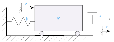
We start with a free body diagram


Energy is stored in the spring and the mass, so we try using the position
"x" and the velocity "v" (v = derivative of x) as our state variables. From this we try to develop our state space model
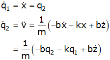
We fail because the last equation has a derivative of the input on the
right hand side. There are systematic ways to choose state
variables to avoid this problem (an example of rewriting a differential
equation with input (i.e., right hand side) derivatives in state space form
is
given here).
Often, an easier way to do this is to find a transfer function and then
convert the
transfer function to state space (described
here). In
this case the transfer function is

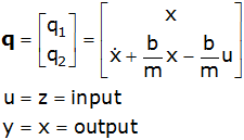
and a state space system (observable
canonic form) is

with
Example: Differentiated Input: Electrical System
The system below has input ei, and output eo. Find a state space
representation.
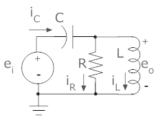
Let's try choosing eo and iL as our state variables.
Energy is stored in the capacitor (voltage) and the inductor (current) so
we try using the capacitor voltage (eo) and the inductor current
(iL) as our state variables.
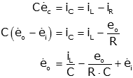
At this point we can see that we have failed because this equation
has the derivative of the input on the right hand side (and we can only have
state variables and inputs in a valid state space representation). There are systematic ways to choose state
variables to avoid this problem (an example of rewriting a differential
equation with input (i.e., right hand side) derivatives in state space form
is
given here).
(Note: we could succeed if we defined our state variables
as q1=eo-ei, q2=iL).
Often, an easier way to do this is to find a transfer function and then
convert the
transfer function to state space (described
here). In
this case the transfer function is

and a state space system (observable
canonic form) is
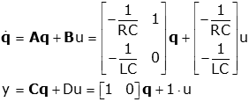
with
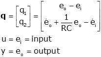
Example: Lower Order System than Expected
Develop as state space representation for the system shown. The
input is fa.

At first glance it might seem that the system is third order because
there are three energy storage elements (two springs and a mass).
However,
because the springs are in series they can be treated as a single element.
Such simplifications are not always so obvious, so let us proceed to develop
a third order state space model.
First we draw free body diagrams
| Freebody at x |
|
Freebody at z |
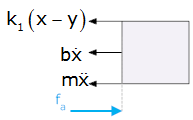 |
|
 |
 |
|
 |
We choose as our state variables:

so

or

While this is a valid state space
system, it is, in fact, only a second order system (the state equations are
not linearly independent; this is shown by the first and third rows being
multiples of each other). The characteristic equation |sI-A|
is only a second order polynomial.
Example: Output is Integral of One of the State
Variables
Consider the system
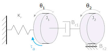
It has been shown that the
system shown can be represented in state space by:


Problem: Find a state space
representation if we want the output to be theta;2.
Solution: Since is not one of the state variables (or an
algebraic sum of the state variables), we need to create another state
variable. Choose as state variables

We now need to write the fourth state variable equation
(which is trivial)

so our state variable system must be expanded to include
this variable

Example: Output is derivative of state variable (Mechanical
Translating)
Derive a state space model for the system shown. The input is fa and the output is z. Note, this system was solved previously, with b and k1 switched.
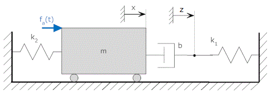
We can write free body equations for the system at x and at y.
| Freebody Diagram |
Equation |
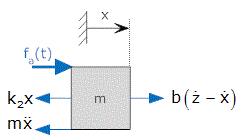 |
 |
 |
 |
There are three energy storage elements, so we expect three state equations.
The energy storage elements are the spring, k2, the mass, m, and
the spring, k1. Therefore we choose as our state variables
x (the energy in spring k2 is ½k2x²), the velocity
at x (the energy in the mass m is ½mv², where v is the first derivative
of x), and y (the energy in spring k1 is ½k1y²).
Our state variables become:

Now we want equations for their derivatives. The equations
of motion from the free body diagrams yield

Clearly there is a problem because the equation for the derivative of q2 has a derivative of a state variable on the RHS. However, we can remove this by substitution in the last equation:
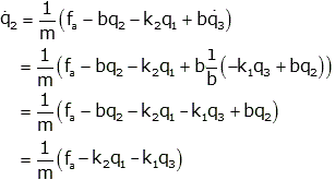
so

with the input u=fa.
References


