There are two fundamental physical elements that make up thermal systems, thermal resistances and thermal capacitance. There are also three sources of heat, a power source, a temperature source, and fluid flow. All five of these are described below, along with the important mathematical relationships used to describe each one.
In practice temperature when we discuss temperature we will use degrees Celsius (°C), while SI unit for temperature is to use Kelvins (0°K = -273.15°C). However, we will generally be interested in temperature differences, not absolute temperatures (much as electrical circuits deal with voltage differences). Therefore we will generally take the ambient temperature (which we will label θa) to be our reference temperature, and measure all temperatures relative to this ambient temperature. We will also assume that the ambient temperature is constant. Thus, if the ambient temperature is =25°C, and the temperature of interest is θi=32°C, we will say that θi=7° above ambient. Note: this is consistent with electrical systems in which we assign one voltage to be ground (and assume that it is constant) and assign it the value of zero volts. We then measure all voltages relative to ground.
Though heat transfer through via conduction and heat transfer via convection occur as a result of very different mechanisms, the resulting mathematical relationship is identical. therefore we will cover both mechanisms here.
Heat flow through an object is determined by several quantities including the thickness of the object (in the direction of heat flow), the area through which heat can flow, and the thermal conductivity (measured in units of W/(m-°K)). We will consider only objects of uniform cross section, with heat flow in one direction (perpendicular to the cross section). Consider the circular cylinder shown below.

A is the area of the cylinder, L is the length of the cylinder, and σ is the thermal conductivity of the cylinder. One end of the cylinder is at temperature θ1 and the other is at θ2, The heat flow from face 1 to face 2 is given by
 |
Note: This is analogous to the electrical equation (with temperature taking the place of voltage, and heat flow taking the place of current). |
where

Note that the resistance increases with length (it is harder for heat to flow), decreases with area (there is more area for the heat to flow through) and decreases with conductivity. Materials like styrofoam have high resistance to heat flow (they make good thermal insulators) while metals tend to have high low resistance to heat flow (they make poor insulators, but transmit heat well).
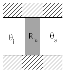
Consider the situation in which there is a wall, one side of which is at the interior temperature, θi, with the other sider at ambient temperature, θa. The wall has a thermal resistance of Ria. This is depicted below in two different, but equivalent, diagrams.


For a thermal resistance, the heat flow through the resistance is given by the temperature difference divided by the thermal resistance. The heat flow is shown by a red arrow below.


There are several things to note about this relationship:
The direction of current flow determines the signs of the temperatures in the equation.
The temperature with the positive sign in the equation is at the tail of the heat flow arrow, and the temperature with the negative sign is at the right. In this way, if θi is greater than θa then the heat flow will be positive to the right (as shown be the arrow).
Higher thermal resistance yields decreased heat flow for the same temperature difference.
Since there are always two temperatures associated with a thermal resistance, it is not appropriate to refer to the temperature of the resistance. Instead, you can refer to the temperature of one side of the resistor or the other.
Given a room in a house that has one wall exposed to the outside (all others are interior walls, with no heat transfer (assuming all interior rooms are at the same temperature)). The wall has a resistance of 0.05°/W.
Note: A problem such as this one will often give the thermal conductivity of the wall. In this case the thermal conductivity would be 20W/°. The thermal conductivity is simply the inverse of the thermal resistance.
Solution:
a) 
b)  C
C
In thermal systems we use θ to represent temperature. The subscript on θ denotes the specific temperature being measured (For example θa might represent the ambient termperature. Thermal resistances always exist between two distinct temperatures. We use "R" to represent the resistance, and two subscripts to denote the two temperatures.
We can use two representations for thermal systems. In the representation (above) on the left, the thermal resistance between interior and ambient is shown as a shaded rectangle. The hash marks above and below the box indicate insulators through which no heat can flow. The only path for heat to flow is from θi to θa.
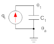
In the representation on the right, temperatures are shown as voltages (with ambient temperature shown as ground since this temperature doesn't change) Thermal resistances (between two temperatures) are shown as electrical resistance, and heat flow is shown as a current.
Each depiction has its own strengths. The depiction at left does a better job of physically describing the system. The description at right is easier to understand and analyze if you have experience with electrical circuits. As systems get more complicated, the circuit is often a more compact and useful representation of a thermal system.
When a fluid impinges on a solid surface that is at a different temperature, heat will flow between them (from hot to cold). If we have a fluid at temperature θ1 impinging on an object at temperature θ2, then we model the heat flow from the fluid to the object as
 with
with

where A=area of the object, and h=coefficient of convective heat transfer (W/(m²·°K)). The coefficient of convective heat transfer is a function of the fluid used (e.g., air and water have very different coefficients) as well as the velocity of the fluid (the coefficient generally increases with the velocity of the fluid).
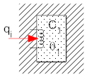
In addition to thermal resistance, objects can also have thermal capacitance (also called thermal mass). The thermal capacitance of an object is a measure of how much heat it can store. If an object has thermal capacitance its temperature will rise as heat flows into the object, and the temperature will lower as heat flows out. To understand this envision a rock in the sun. During the day heat goes in to the rock from the sunlight, and the temperature of the rock increases as energy is stored in the rock as an increased temperature. At night energy is released, and the rock cools down. We represent a thermal capacitance in isolation in diagrams (and equations) as shown below (in the drawing at the left the coil represents a power source, see below, and the stippled object is the thermal capacitance). In the thermal analog, one end of the capacitor is always connected to the constant ambient temperature.


Note: the electrical model will always have one side of the capacitance
connected to ground, or ambient. Also, we could write the equation as
 but since θa is constant,
it can be removed from the derivative.
The thermal capacitance of an object is determined by its mass and specific heat

where "C" is the thermal capacitance, "m" is the mass in kilograms, and "cp" is the specific heat in J/(kg-°K). It is always assumed that the capacitor is at a single uniform temperature, though this is obviously a simplification in many cases.
The specific heat of water is 4.2 kJ/kg-°C.
Solution:
a) C=m·cp, and 5 liters of water has a mass of 5 kg. So C = 5·(4.2·103) = 21 kJ/°C.
b) First, calculate the rate of increase of temperature

then find the total increase:

so the final temperature is

A common part of a thermal model is a controlled power source that generates a predetermined amount of power, or heat, in a system. This power can either be constant or a function of time. In the electrical analog, the power source is represented by a current source. An example of a power source is the quantity "qi" in the diagrams for the thermal capacitance, above. In practice a power source is often an electrical heating element comprised of a coil of wire that is heated by a current flowing through it. Therefore we use a diagram of a coil of wire to represent the power source. An ideal power source generates power that is independent of temperature. Examples of power sources you might be familiar with are electric hair dryers (typically on the order of 1000 W) and space heaters for individual rooms (typically several hundred Watts).
Another common source used in thermal systems is a controlled temperature source that maintains a constant temperature. An ideal temperature source maintains a given temperature independent of the amount of power required. A refrigerator is an example of such a source. Another such source is the ambient surroundings. We will assume that the temperature of the ambient surroundings is constant regardless of the heat flow in or out (we will also take ambient temperature to be our reference temperature, i.e., θa=0°).
If fluid with specific heat "cp" J/(kg-°K) flows into a system with a flow rate of "G" kg/sec and a temperature of "θin" °C above ambient, and flows out at a temperature of "θout" °C below ambient then the rate of heat flow into the system is given by

We can cancel the °K and °C since a temperature difference (θin-θout) is the same in Kelvin or Celsius
If you carefully observe this equation, it makes sense intuitively. Heat into a system goes up with mass flow rate into the system (increased mass flow, yields increased heat flow). Heat into a system also goes up with the specific heat of the mass (higher specific heat indicates increased capacity to store heat). Finally, heat into a system increases with an increased inflow temperature , or a decreased outflow temperature (if the temperature difference between inflow and outflow increases, more heat is being taken from the fluid). Note: the mass flow rate at the input and output must be equal or the mass (and thermal capacitance) of the system would be changing. This is not allowed for the systems being studied (time-invariant systems).
| Quantity | Equation | Note |
| Temperature | none | Temperatures in equations are relative to ambient, and results are °C (or °K) above ambient. |
| Resistance |  |
The heat flow through the resistance is proportional to the temperature
difference, and inversely proportional to the value of the resistance. A thermal resistance exists between two separate temperatures, one on either side. These temperatures are indicated by the two subscripts of the resistance. |
| Capacitance |  |
The rate of change of temperature of a thermal capacitance is proportional
to the heat flow into it and inversely proportional to the its value. The capacitance is at a single, uniform, temperature. |
| Power Source | none | A power source generates a specified power, and the amount of power is independent of temperature. |
| Temperature Source | none | A temperature source maintains a specified temperature, and this
temperature is independent of heat flow in or out of the source. |
| Mass Transfer |  |
The amount of heat going into a system due to fluid flow is proportional
to the fluid's mass flow rate (G), specific heat (cp), and the temperature differential between the inflow and outflow (θin- θout). |
© Copyright 2005 to 2019 Erik Cheever This page may be freely used for educational purposes.
Erik Cheever Department of Engineering Swarthmore College